


7
Compressor Operation
CONTROL RELAY (CR) — This relay provides information
to the processor about compressor operation (one control relay
per compressor). The relay controls and protects the compres-
sor and also controls the crankcase heater.
A control signal to check the safety statuses and to start the
compressor is sent from the relay board. This signal travels
through all of the safeties: the high-pressure switch, and the in-
ternal protector (where used) and on to the control relay coil.
Once the control relay coil has been energized, the control re-
lay completes a feedback circuit for the processor, informs the
processor of the status of the compressor safeties, energizes the
compressor contactor coil, and deenergizes the crankcase heat-
ers. A fault will be detected by the processor if the control relay
opens during operation or startup. The processor will lock the
compressor or the circuit off by deenergizing the appropriate
relay(s) on the relay board and energizing an alarm signal.
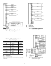
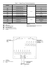
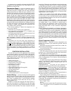
Accessory Board —
The accessory board is standard
(factory supplied) in the VAV rooftop units. See Fig. 15. This
board is located in the control box of each unit. Each board has
a prewired connector supplied with it to connect directly to the
processor board. It has 3 potentiometers: P3, P5, and P6.
P3 — RESET LIMIT — The processor board is programmed
for occupied space temperature reset. In order for reset to
work, the accessory temperature reset board must be used.
Potentiometer P3 is the maximum set point temperature to
which the supply air can be reset.
P5 — ECONOMIZER MINIMUM POSITION — This
potentiometer controls the set point for the minimum position
of the economizer.
P6 — MORNING WARM-UP TEMPERATURE — This
potentiometer controls the morning warm-up temperature set
point.
Single-Step Demand Limit —
The single step de-
mand limit provides a means to limit the capacity of the VAV
unit using an external switch. Single step demand limit will
limit the compressor displacement based on the ratio of the
wiper arm to the full scale resistance. The exact percentage of
capacity reduction differs depending on the number of capacity
steps.
A 3-wire, 5 to 20 Kohm, field-supplied potentiometer (P4)
is required for this option. The potentiometer should be wired
to the processor J3 connections. In order to control the demand
limit, the wiper arm of the potentiometer should be switched
open and closed based on the demand limit requirement. The
control switch is also field-supplied and installed.
If the wiper arm wire is open, all capacity stages can be
used. When the wiper arm wire is closed, the capacity is re-
duced by the amount set on potentiometer P4.
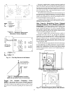
Demand Limit Control Module (DLCM) —
The
DLCM provides a 2-step demand limit control using an exter-
nal switch. The first step is between 50% and 100% of the
maximum compressor displacement. See Fig. 16. The second
step is between 0% and 49% of the maximum compressor dis-
placement. The exact percentage differs depending on the
number of capacity steps.
Two adjustable potentiometers are used to set the 2 demand
limit points. Potentiometer P1 is used to set a demand limit
between 50% and 100% of the unit capacity. Potentiometer P2
is used to set a demand limit between 0% and 49% of unit
capacity.
If no power is supplied to the demand limit control module,
all capacity stages can be used. When power is supplied to ter-
minal IN1 only, the first step of the demand limit control is en-
ergized and the capacity is reduced by the amount set on poten-
tiometer P1. When power is supplied to terminal IN2 only, or
to both IN1 and IN2, the capacity is reduced by the amount set
on potentiometer P2.
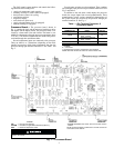
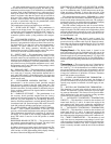
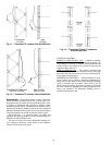
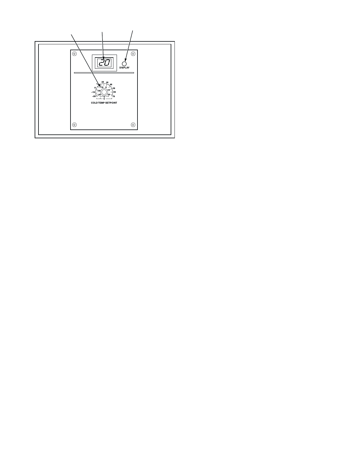
TWO-DIGIT
DISPLAY
DISPLAY
BUTTON
P1 SUPPLY AIR
SET POINT
POTENTIMETER
Fig. 6 — Display/Set Point Board