


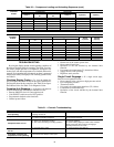
44
Table 20 — Compressor Loading and Unloading Sequences (cont)
TROUBLESHOOTING
By using the display module, actual operating conditions of
the unit are displayed while it is running. The Quick Test func-
tion allows proper operation of compressors, compressor un-
loaders, fans, and other components to be checked while unit is
stopped. If an operating fault is detected, an alarm is generated
and an alarm code(s) is displayed. For checking specific items,
see Table 21.
Checking Display Codes —
To view the digital dis-
play codes, press the button located to the right of the LED dis-
play/set point board in the control box. See Table 22 for Opera-
tional Status Codes. See Table 23 for Diagnostic Codes.
Complete Unit Stoppage —
If the unit is off, there are
several conditions that can cause this situation to occur:
• Remote ON/OFF circuit in Unoccupied mode.
• Unit ON/OFF switch moved to OFF position.
• Programmed schedule at the timeclock.
• General power failure.
• Blown fuse in the control power feed.
• Open control circuit fuse.
• Operation of the unit blocked by the demand limit
function.
• Unit supply-air temperature (T1) thermistor failure.
• Supply-air fan is not operating.
• High duct static pressure.
Single Circuit Stoppage —
If a single circuit stops,
there are several potential causes:
• Open contacts in the compressor high-pressure switch.
• Low refrigerant pressure.
• Thermistor failure.
• Unit supply-air temperature thermistor (T1) failure.
• Compressor circuit breaker trip.
• Operation of the circuit blocked by the demand limit
function.
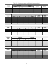
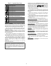
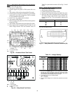
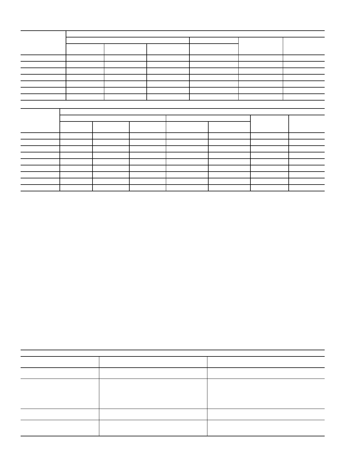
Table 21 — Controls Troubleshooting
COOLING
STAGE
SIZE 088 UNITS
Lead Circuit Lag Circuit
Active
Cylinders
Percent
Capacity
Comp 1
Unloader
U1
Unloader
U2
Comp 2
0
OFF OFF OFF OFF 0 0
1
ON ON ON OFF 2 16
2
ON ON OFF OFF 4 33
3
ON OFF OFF OFF 6 50
4
ON ON ON ON 8 66
5
ON ON OFF ON 10 83
6
ON OFF OFF ON 12 100
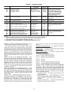
COOLING
STAGE
SIZE 104 UNITS
Lead Circuit Lag Circuit
Active
Cylinders
Percent
Capacity
Comp 1
Unloader
U1
Comp 3 Comp 2 Comp 4
0
OFF OFF OFF OFF OFF 0 0
1
ON ON OFF OFF OFF 4 20
2
ON OFF OFF OFF OFF 6 30
3
ON ON OFF ON OFF 10 50
4
ON OFF OFF ON OFF 12 60
5
ON ON OFF ON ON 14 70
6
ON OFF OFF ON ON 16 80
7
ON ON ON ON ON 18 90
8
ON OFF ON ON ON 20 100
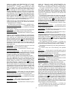
SYMPTOM(S) PROBABLE CAUSE(S) SOLUTION(S)
Controls do not seem
to be operating.
Remote on-off function may be
keeping controls off.
Check status.
Evaporator fan does not run.
1. Circuit breaker open.
2. Inverter overload (if equipped).
1. Find cause and reset circuit breaker.
2. Find cause and reset.
Compressor does not run.
1. Circuit breaker is open.
2. There is no demand for cooling.
3. The control is locking out cooling operation.
4. Demand Limit in effect.
1. Find cause and reset circuit breaker.
2. Correct operation.
3. Check rotating display for alarm codes. Resolve
alarm cause and reset control by changing to
standby and back to run mode.
4. Check Demand Limit Settings.
Condenser fans do not
turn on.
Circuit breaker is open. Find cause and reset circuit breaker
Cooling demand exists and
economizer modulates, but
compression is not operating.
Compression cannot be initiated
until economizer damper is 90% open.
Correct operation.