


23
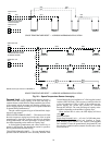
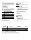
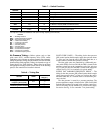
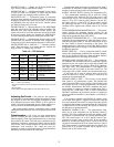
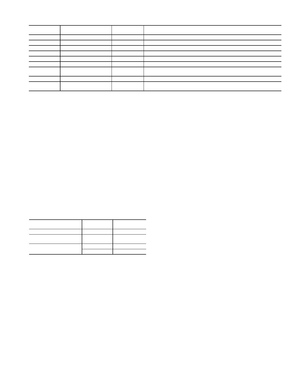
Table 7 — Switch Functions
*Not required on 48FM and 50FM,FS units (units with high capacity power exhaust).
LEGEND
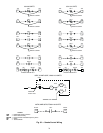
Air Pressure Tubing —
Before options such as inlet
guide vanes (IGV), variable frequency drive (VFD), and/or
modulating power exhaust can operate properly, the pneumatic
tubing for pressure sensing must be installed. Use fire-retardant
plenum tubing (field-supplied). Tubing size depends on type of
control device (see Table 8 below). Tubing must be run from
the appropriate sensing location (in the duct or in the building
space) to the control device location in the unit.
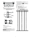
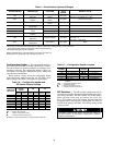
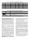
Table 8 — Tubing Size
INLET GUIDE VANES — The tubing for the duct pressure
(DP) control option should sample supply duct pressure about
2
/
3
of the way out from the unit in the main trunk duct, at a
location where a constant duct pressure is desired.
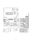
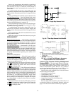
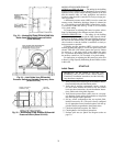
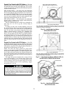
The inlet guide vanes are controlled by a differential pres-
sure switch (DPS). On sizes 034-048, the DPS is located in the
auxiliary control box at the economizer end of the unit (see
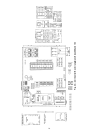
Fig. 33). On sizes 054-104, the DPS is located in the supply fan
section. See Fig. 34. Use a nominal
3
/
8
-in. plastic tubing.
SUPPLY FAN VARIABLE FREQUENCY DRIVE — The
tubing for the duct pressure (DP) control option should sample
supply duct pressure about
2
/
3
of the way out from the unit in
the main trunk duct, at a location where a constant duct pres-
sure is desired.
The duct pressure is sensed by a pressure transducer. The
pressure transducer output is directed to the VFD. On 034-048
units the DP transducer is located in the auxiliary control box.
On 054-104 units, the DP transducer is located in the supply
fan section. See Fig. 34. Use a nominal
1
/
4
-in. plastic tubing.
SWITCH
NUMBER
CONFIGURATION VOLTAGE FUNCTION
SW-1
N.C. 115 Deenergize 115-v (OFC, Comp, IFC, Electric Heaters)
SW-2
N.C. 115 Deenergize TRAN7 (Process Board)
SW-3
N.O. 24 Energize EOR (Open Economizer Outside Air Dampers)
SW-4
N.O. 115 Energize IFC and CR-3 (IGV/VFD)
SW-5
N.C. 115 Isolate IFC and PEC for Separate Operation
SW-6
N.O. 115 Energize PEC (Power Exhaust)
SW-7
N.O. 24
Open PED at DPS (48FK,JK and 50FK,JK Units) Force Power Exhaust VFD
to Maximum Speed (48FM and 50FM,FS Units)
SW-8*
N.C. 24 Block Auto-Close at DPS (Due to Low BP)
SW-9A/B
A: N.O.
B: N.C.
115 max Signal Room Terminals to Open (HIR1)
BP —
Building Pressure
DPS —
Differential Pressure Switch
EOR —
Economizer Open Relay
HIR —
Heat Interlock Relay
IFC —
Indoor Fan Contactor
IGV —
Inlet Guide Vane
N.C. —
Normally Closed
N.O. —
Normally Open
PEC —
Power Exhaust Contactor
PED —
Power Exhaust Damper
OFC —
Outdoor Fan Contactor
VFD —
Variable Frequency Drive
OPTION UNITS
NOMINAL TUBE
SIZE (in.)
Inlet Guide Vanes (IGV)
ALL
3
/
8
Supply Fan Variable
Frequency Drive (VFD)
ALL
1
/
4
Modulating Power Exhaust
FK,FKX,JK,JKX
3
/
8
FM,FS
1
/
4