


5
Dependencies
— Water Economizer option is enabled, and
Fan is On, and Inlet Water Temperature is below set point; or
from “Remote Scheduler,” or from “Remote Linkage.”
Economizer mode is switched to Off or no start if: there is
no condenser waterflow, Fire Input is On, Fan is not On, or Un-
occupied mode is On.
Variable Waterflow Systems
— Whenever water economizer
is off, the economizer flow control valve is fully closed, and the
reverse flow valve directly to the condenser is fully open. Upon
engagement of the water economizer, the economizer flow con-
trol valve shall be controlled to maintain the MA_RA located
between the economizer coil and the DX cooling coil, at a tem-
perature near the supply air set point. The the reverse flow valve
will be controlled in reverse of the economizer flow control
valve’s position. The following formula is an example: Reverse/
Head Press Ctrl output = 100 – two-position/Econo output.
When the unit is off, both valves are closed.
Constant Waterflow Systems
— Control of the economizer
flow control valve is same as for variable waterflow systems.
Control of the reverse flow control valve position will inversely
track the economizer flow control valve, such that the total sum
of the two valves open positions always equals 100%. The only
difference between the variable waterflow system and the
constant waterflow system is that for the constant flow system
when the unit is off, the economizer valve will be closed and
the reverse flow control valve will be open.
WATER ECONOMIZER COIL (50BV) — For the 50BV
unit, this factory-installed option contains a water-to-air coil, a
two-position diverting valve, and related piping. The water econ-
omizer is controlled by an Aquastat and a return-air thermostat.
HEATING COILS AND VALVE (50XJ PCB2) — Water or
steam heating options are factory installed. Each includes a
motorized, variable control water or steam flow control valve,
which can be factory supplied for field installation outside the
unit. Installed in the water or steam inlet pipe, this valve is
wiredtotheunitmaincontrollerandoperatesona4to20mA
signal. A Heating mode PID control is needed to control the
valve position (i.e., coil heating capacity) variably between 10
and 100%. The PID will control a set point to + 1° F; for VAV
Units this set point is at the Supply Air Temperature Sensor, or
as communicated from a remote thermostat.
HEAD PRESSURE CONTROL (50XJ PCB2) — Head Pres-
sure Control is required for unit installations that will
experience entering condenser water temperatures of 55 F or
lower.
NOTE: Head Pressure Control is not needed or used in
conjunction with a Water Economizer. A refrigerant pres-
sure transducer will monitor head pressure on compressor
circuit 1, allowing the unit main controller to regulate water
flow rate in the main water line entering the unit; i.e., flow
to all condensers. (Water header design to the condensers
will be optimized such as to provide relative flow rates to
each condenser based on its compressor capacity, enabling
successful waterflow control at the main entering pipe.)
There are two possible water valving configurations, as
outlined below.
Pressure transducer input is factory installed in the
discharge line of compressor circuit 1. It is provided 5 vdc by
the unit main controller and returns a signal 1 to 5 vdc linearly.
The sensor’s range is 0 to 550 psig.
Water Valve(s) Control
Variable Building Waterflow Systems — Variable waterflow
configurations use only one water valve in the main water
supply pipe. The factory installed valve is a normally open
motorized variable control type. The valve is controlled by a
4 to 20 mA signal from the main unit controller using the
Reverse/Head Press Ctrl output, which modulates to maintain
the head pressure set point (Setpoint 04).
Constant Building Waterflow Systems — Constant waterflow
configurations use two (2) water valves, only one of which is
in the main water supply pipe. The second valve is located in a
bypass pipe to the main outlet water pipe branched off of the
supply pipe immediately ahead of the first valve. This valve is
same type, but normally closed and is controlled in unison with
the first valve, but opposite position, such that the total opening
of the 2 valves always equals 100%.
VFD BYPASS (50XJ PCB2) — The VFD Bypass option
provides backup for the VFD Drive in VAV units. It uses a
manually operated rotary switch, which includes a series of
high voltage contacts. The bypass is a direct input to the unit
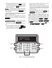
controller, and will be activated via a switch on the unit front
panel. When manually activated, the rotary switch takes the
VFD out of the fan power circuit and provides the 3-phase
power directly to the fan motor, running it at constant speed. A
low voltage control circuit ensures that the unit controller pro-
vides a signal to allow all VAV dampers to open fully before
the fan is turned on (at constant/full speed). A blue indicator
light located on the front of the unit indicates that the VFD By-
pass is active. A High Duct Static Switch (HDS) shuts the fan
down if duct static exceeds a maximum setting.
VENTILATION OUTPUT (50XJ PCB2) — The ventilation
output is controller output signal (available for field connection)
to a field-supplied ventilation damper(s). This signal is activated
whenever the unit is in the occupied mode.
SPACE TEMPERATURE SENSOR (50XJ PCB2) — A field-
supplied Carrier space temperature sensor is required to
maintain space temperature in sensor mode.
SUPPLY AIR RESET (50XJ PCB2) — Supply air temperature
set point may be reset using either the SPT or MA_RA.
SUPPLY AIR RESET (50BV) — Reset is provided by a
field-installed temperature sensor.
EXHAUST FAN CONTROL OUTPUT (50XJ PCB2) — This
output is activated whenever the unit is in the Occupied mode.
This is a modulating output that controls based on the Building
Pressure Input set point.
CONDENSER WATER PUMP/WATER TOWER (50XJ
PCB2) — This output (provided for field connection) is used
to control condenser water flow. Either an On/Off signal or a
variable output may be required for this feature.
PHASE LOSS/REVERSAL PROTECTION SWITCH
(50XJ PCB2) — This switch monitors VFD/Fan Motor sup-
ply leads to detect phase loss or reversal. If the switch detects
improper phasing, an input is sent to the unit controller, which
shuts the unit down. After a time delay, the controller attempts
to restart the unit.
A phase loss/reversal switch may be installed in the unit to
detect over/under voltage conditions and phase loss or reversal.
When the switch opens, the controller outputs are forced to off
with Safety forces, the alarm output will close and the red
alarm light will be lit. A system alarm will be generated and
displayed on the unit keypad. Unit reset is automatic when the
voltage and power phases have been restored.
FREEZE THERMOSTAT (FREEZSTAT) (50XJ PCB2) — The
Economizer Freezestat, used in conjunction with an optional
water economizer coil or heating coil, is a factory installed
averaging (capillary tube) air temperature sensor positioned in
the unit inlet airstream.
If the freeze protection switch contacts open the ventilation
request output will be closed for 15 minutes and the warning
light will light. If the freeze protection switch contacts are still
open after 15 minutes the supply fan will be stopped, all
compressor cooling will stop, the economizer valve will open
to 100%, the pump request output will remain on, and the
alarm light will light. This will maintain condenser water flow
through the coil to prevent freezing the coil while stopping all
other operations that could have contributed or will be affected