


27
TROUBLESHOOTING
Refer to Tables 17-21 for troubleshooting information.
Run Test Troubleshooting — The automatic run test
is a diagnostic tool used during unit start-up. Table 17
describes troubleshooting specifically for the automated run
test.
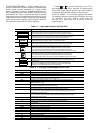
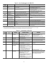
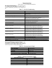
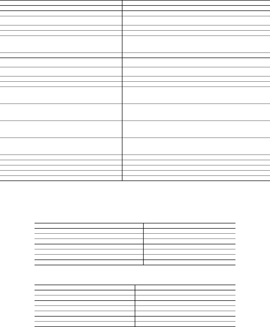
Table 17 — Run Test Troubleshooting
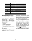
Forcing and Clearing an Input or Output — Dur-
ing unit operation and/or troubleshooting, it may be necessary
or desirable to clear an input or output. Tables 18 and 19
describe the procedure for clearing inputs and outputs.
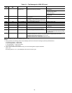
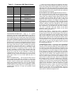
Table 18 — Forcing an Input or Output
Table 19 — Clearing a Forced Input or Output
PROBLEM POSSIBLE CAUSE
Control modules do not have lights when unit power on. Transformer open. Circuit breaker open. Power wiring open. Module failure.
Control display does not light up when unit power on. Connection location. Interface cable open. Display failure.
Run test will not start. Pre-existing ALARM (red)? Not “Logged in” with password.
Switch not in Local.
WARN (yel) does not light during run test. Wiring open. Lamp failure. Control module failure.
ALARM (red) does not light during run test. Wiring open. Lamp open. Control module failure.
Run test stops, ALARM (red) light is lit after it blinks once. Bypass switch to LINE. Mode switch to OFF. Duct high
pressure switch open. Fire shutdown input or jumper open.
Supply air temp out of range. Duct static pressure sensor out of range.
Compressor resistor board wiring error or failure.
Fan does not start/ALARM (red) blinks 2 times. Fan relay failure.
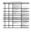
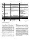
Run test stop, ALARM (red) light is lit after blinking 3 times. Wiring open. VFD connection error. VFD setup error. Fan relay failure.
Current isolator failure. Control module failure.
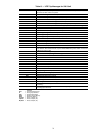
Run test stop, ALARM (red) is lit after it blinks 4 times.
Fan does not increase speed.
VFD connection error. VFD setup error.
Current isolator load adjustment too low.
Fan does not stop after ALARM (red) blinks 5 times. Fan relay failure.
Fan rotation is backwards. VFD to motor wiring sequence error. VFD setup error.
Run test stop, ALARM (red) is lit after blinking 6 times.
Compressor 1 does not start.
Wiring open. Compressor resistor board wiring error or failure.
High-pressure switch, low-pressure switch, coil frost switch,
or compressor protection module open. Compressor relay failure.
Contactor failure. Control module failure. No refrigerant charge.
Run test stop, ALARM (red) is lit after blinking 7 times.
Compressor 2 does not start.
Wiring open. Compressor resistor board wiring error or failure.
High-pressure switch, low-pressure switch, coil frost switch,
or compressor protection module open. Compressor relay failure.
Contactor failure. Control module failure. No refrigerant charge.
Run test stop, ALARM (red) is lit after blinking 8 times.
Compressor 3 does not start.
Wiring open. Compressor resistor board wiring error or failure.
High-pressure switch, low-pressure switch, coil frost switch,
or compressor protection module open. Compressor relay failure.
Contactor failure. Control module failure. No refrigerant charge.
Run test stop, ALARM (red) is lit after blinking 9 times.
Compressor 4 does not start.
Wiring open. Compressor resistor board wiring error or failure.
High-pressure switch, low-pressure switch, coil frost switch,
or compressor protection module open. Compressor relay failure.
Contactor failure. Control module failure. No refrigerant charge.
Compressor rotation is backwards. Field power wiring sequence error. Compressor power wiring sequence error.
“C” message in I/O status display. No input signal/communication failure.
“Service” message in I/O status display. Value is forced from 6400 keypad entry.
“Supervisor” message in I/O status display. Value is forced from network communication (i.e., PC).
ALARM (red) always on, will not enter run test. SAT, DSP, CSMUX, DHS, or PHASE input values out of range. Mode switch OFF.
STEP # INSTRUCTION/ACTION RESULT
1. Press 3, SET, ENTER “Controller Password”
2. Press ENTER “Log in to Controller” “Enter Password”
3. Press 1111, ENTER “Log in to Controller” “Logged in”
4. Press STAT “Hardware Points”
5. Press ENTER “Supply Air Temperature”
6. Press down arrow to obtain desired item (NOTE: order is PCB1 I/O, PCB2 I/O, PCB3 I/O)
7. Key in force value (1=on/start, 0 = off/stop), ENTER force value/status “Service”
STEP # INSTRUCTION/ACTION RESULT
1. Press 3, SET, ENTER “Controller Password”
2. Press ENTER “Log in to Controller” “Enter Password”
3. Press 1111, ENTER “Log in to Controller” “Logged in”
4. Press STAT “Hardware Points”
5. Press ENTER “Supply Air Temperature”
6. Press down arrow to obtain desired item (NOTE: order is PCB1 I/O, PCB2 I/O, PCB3 I/O)
7. Press CLEAR, ENTER auto value/status (NOTE “Service” must be gone)