


16
OPERATION
Occupancy Determination —
The OMNIZONE™
controller can determine occupancy in many ways. Local occu-
pancy is determined by either a local schedule contained in the
CC6400 controller, the use of the ROCC discrete input point or
by setting the Local/Off/Remote switch to Local. In order for
the CC6400 schedule or ROCC point to function the Local/
Off/Remote switch must be set to Remote.
When the OMNIZONE unit is connected to a Carrier
Comfort Network and the Local/Off/Remote switch is set to
Remote, the controller occupancy can be determined by a
Network Group schedule, a Network Global schedule, or via
Linkage from a linkage device such as a ComfortID™ linkage
master.
Fan Control — All Variable Air Volume (VAV) units have
a Variable Frequency Drive (VFD) to provide variable fan
motor speed and thus variable airflow. Fan control turns the fan
on and off based on unit operating mode, and controls fan
speed to maintain a particular duct static pressure at a Duct
Static Pressure Sensor (DSP). The objective is to maintain a
reasonably constant supply-air exit velocity at VAV system
outlet grilles, regardless of damper opening positions. The duct
static pressure sensor is field-installed about
2
/
3
of the way
toward the “far end” of the ductwork. A High Duct Static
Switch (HDS) provides protection by shutting the fan down if
the duct static pressure exceeds a maximum setting.
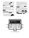
For the 50XJ unit, a VFD interface display is mounted in
the front of the unit. A number of user-adjustable features can
be entered/changed using the keypad on the display. These
features described in detail in the Variable Frequency Drive
Control section.
Sequence of Operation — The following control
sequence of operation for the 50XJ,BV unit describes the
various sequences that occur depending upon the way an
operation is triggered and which software control points are
involved.
SUPPLY FAN — The Supply fan can be activated in any of
the following ways:
• Unoccupied space or return air temperature demand.
• Unoccupied Linkage demand.
• Local Time Schedule (TIMCLOCK software point).
• Remote Occupancy (ROCC software point).
• By placing the remote-off-local switch in the local
mode.
• Enabled by Schedule.
Once one of the above conditions exists, either TIME-
CLOCK or ROCC indicates ON or Enable. The software point
OKFAN will turn on followed by the points TRMCT for air
terminal control and PUMP and TOWER to request condenser
water flow and temperature control. Approximately 20 to
30 seconds later the supply fan (SF) point will turn ON and the
VFD output SPEED will increase. The SPEED point will
output a signal, determined by a PID calculation, based on the
duct static pressure DSP input and the Supply Static Pressure
set point in SETPT05.
Once the supply fan is running and the static pressure
increases above the Supply fan status set point in SETPT01, the
supply fan status point (SFS) will indicate ON and the software
point SF_SFS will indicate TRUE.
Enabled By Unoccupied Demand
— A software point “Space
Control Point” will display the current value of the sensor used
to determine unoccupied demand. The EWT sensor provides
this function for the 50BV unit. The display is based on the
sensors installed and the configuration of these sensors in the
custom configuration, or the status of linkage.
If the Return/Mixed air sensor is in the mixed airstream and
configured as such and there is no Space temperature sensor
installed and no Linkage, the Space Control Point will display
a default value of 75 F, which is above the default occupied
cooling set point and below the unoccupied cooling set point.
If this condition exists, supply air reset from a sensor and
unoccupied unit operation will not occur.
If the unit is configured to use a sensor for the Space
Control Point or if Linkage is active and the space has
unoccupied demand, the software point OKFAN will turn on
followed by the points TRMCT for air terminal control and
PUMP and TOWER to request condenser water flow and
temperature control. Approximately 20 to 30 seconds later the
SF point will turn ON and then the VFD output SPEED will
increase. If unoccupied demand is the reason the fan is on, a
control force will appear next to the OKFAN point. Otherwise
there should not be a force on that point.
If the fan is running due to unoccupied heating or cooling
demand, either the space temperature (if installed), return air
temperature or average linkage temperature must rise or drop
to within half way between the occupied and unoccupied set
points in order for the fan to turn back off.
Enabled by Switching to Local Mode
— When the switch is
placed in the local mode the ROCC point will indicate enable.
If ROCC is ENABLED a software routine will override the
occupancy schedule so that TIMECLOCK will also turn on.
When ROCC is turned off the TIMECLOCK point will turn
off within 60 seconds.
Supply Fan Shutdown
— If the unoccupied demand is satis-
fied and TIMECLOCK and ROCC are off and disabled,
OKFAN will turn off, SF_SFS will turn off, Tower and PUMP
will turn off, and then 5 minutes later the SF point will turn off
and the VFD speed will go to 0%.
During the 5-minute delay, the cooling and heating routines
become disabled. This delay allows a compressor that may
have just started to run for its 5-minute minimum on time with
the supply fan on. For example, if the staging routine had just
started Compressor 3 at the time the OK_FAN point changed
to OFF, the cooling routine would become disabled and com-
pressors 1 and 2 would shut off right away. Compressor three
would continue to run for its minimum on time of 5 minutes.
The fan continues running until all compressors meet the
minimum on time and run with a load, preventing them from
shutting down due to a safety.
Supply Fan operation with Optional Bypass (50XJ)
—Ifthe
optional VFD Bypass is installed and the Bypass switch has
been turned to Bypass, and the access panel is in place, the
software point Bypass access panel secure BB_SAFE has been
turned to ON, and the unit operation switch has been placed
back in local or remote, then the bypass start stop point BPS_S
will follow the SF point when it turns on and off. The terminal
open point TRMOP will go on with the TRMCT point before
the fan starts.
COMPRESSOR COOLING — If the fan is on and there is no
demand for Heat, the equipment mode (MODE) will be
COOL, and Cooling (COOLOK) will switch to ENABLE.
If the unit is configured for variable flow the Reverse/Head
Pressure CTRL valve will open (otherwise it will already be
open), and if there is condenser water flow (CDWF is YES),
then the Fan + Condenser water flow point will become TRUE
and the Compressor Cooling (COMRES) point will switch to
Enable.