


22
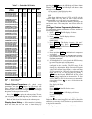
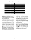
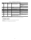
Table 14 — VFD Mode Summary for 50XJ Unit
50BV Variable Frequency Drive Control — The
variable frequency drive is factory wired and programmed for
proper operation with the unit controls; no installation or
service adjustments are normally required.
The VFD default conditions at unit power up are: “0.0 Hz”
in the LED display. When the fan is operating, the LED
displays the output frequency in Hz.
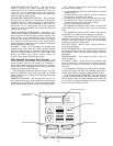
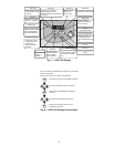
OPERATING KEYPAD — The keypad allows users to en-
able or disable the keypad, input commands from the keypad,
and monitor drive operation. Fig. 7 shows the operating panel
keypad layout and the locations of the keys and display LEDs.
The 4-character LED displays various values, depending
upon what mode is running.
• In Standard Monitor mode: the LED displays the current
output frequency.
• In Status Monitor mode: monitors the status conditions
and frequency command value setting.
• In Setup mode: displays setup parameter titles and values.
• During a trip: displays the trip title.
The appropriate local/remote LED, which is inset into the
speed control key, is lit when the unit is in local or remote
mode.
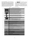
KEY FUNCTIONS — Refer to Fig. 8 for the functions of
each key on the keypad.
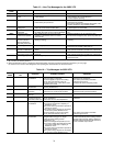
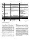
NON-TRIP MESSAGES — Non-trip messages are those that
may be displayed but do not cause a trip and are not recorded in
the fault history. Table 15 lists the non-trip messages with their
explanations.
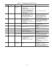
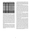
TRIP MESSAGES — Trip messages and their causes are
shown in Table 16.
CLEARING A TRIP — A trip clear can be performed after
the cause of the trip has been removed. To perform a trip clear,
either switch off power to the inverter (keep VFD off until
charge LED turns off) or use the following procedure:
Press STOP. The display will show: CLr. Press STOP again.
The display will show: 0.0, indicating that the trip is cleared
and the display will return to Standard Monitor mode.
If any key other than the STOP key is pressed at the trip
clear command prompt, the trip clear command is aborted and
the display returns to Standard Monitor mode (where the trip
title will be displayed flashing). The trip clear command does
not clear the recorded past faults.
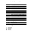
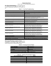
STATUS MONITOR MODE — In Status Monitor mode, it is
possible to monitor the inverter status (frequency command,
output voltage, current, terminal information, etc.). Status
monitor mode is entered by pressing the MON key until the
monitor LED is lit. The present output frequency (which, just
after power is applied, is 0.0) is displayed. (If the ST-CC
terminals are not shorted, OFF will be displayed.)
If either or is pressed continuously, every 0.5 sec
the next/previous item will be displayed. As optional points,
RUN, STOP, displaying the frequency status, and switching to
local/remote and manual/auto modes can be performed.
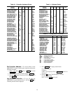
KEY OPERATON LED MESSAGE EXPLANATION
— 0.0 Standard monitor mode
S/P/M SEtP Switch to mode selection menu.
S/P/M PrG Program mode.
S/P/M non Select Status Monitor mode title with U/D keys.
R/W Fr-F Enter Status Monitor mode by pressing R/W. First monitor
item (motor run direction) is displayed.
DOWN 60.0 Pressing UP/DOWN views next/previous status variable.
Frequency command value displayed (monitor #1)
DOWN C 0 Load current (%) monitor (monitor #2)
DOWN Y 228 Input voltage (V) monitor (monitor #3)
DOWN P 0 Output voltage (V) monitor (monitor #4)
DOWN A.... Input terminal status monitor
DOWN b.... Input terminal status monitor
DOWN O.... Output terminal status monitor
DOWN t0.00 Total RUN time monitor
DOWN OC1 Past trip #1 monitor
DOWN OC2 Past trip #2 monitor
DOWN OC3 Past trip #3 monitor
DOWN nErr Past trip #4 monitor
DOWN Fr-F Return to the top menu item