


17
COMRES triggers the compressor staging routine that
controls the number of compressors energized. Units are
equipped with 4 compressors piped in separate refrigerant
circuits, and staged On/Off in a fixed sequential manner
(compressor no. 1 through compressor no. 4). The compressor
control routine uses a PID calculation to determine the percent-
age of cooling required, from 1 to 100%. Demand for the PID
calculation is determined from the supply air temperature and
the supply air set point (SETPT06).
Compressor cooling (COMPRES) will be turned off for any
of the following reasons:
• There is no condenser water flow (CDWF is Off).
• Economizer Freezestat (FREEZ) has been in alarm for
more than 15 minutes.
• MODE changes to heat.
• OK-FAN turns off during normal shut down.
• During normal compressor operation the minimum on
time is 5 minutes and the minimum off time is 5 min.
ECONOMIZER COOLING (50XJ) — The unit diverts con-
denser inlet water flow through an optional economizer coil to
precool evaporator entering airflow. This occurs when there is
demand for the cooling, and the temperature at an Entering
Water Temperature (EWT) thermistor is colder than the
economizer start set point. Waterflow is controlled via two
electronic water flow valves. This option also incorporates an
Economizer Freeze Switch (EFS), located at the inlet of the
economizer coil.
Economizer water flow is in series with the condensers
allowing compressor operation while the economizer is
operating.
If the Fan is on, and there is no demand for heat then the
equipment mode (MODE) will be COOL and Cooling
(COOLOK) will switch to ENABLE.
If the unit is configured for variable flow the Reverse/Head
Pressure CTRL valve will open (otherwise it will already be
open), and if there is condenser water flow (CDWF is YES)
then the Fan + Condenser water flow point will become TRUE.
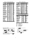
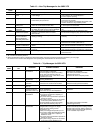
If the entering-water temperature is below the Economizer
start set point in the configuration parameters table (Table 10),
then the Mod. Econ Enabled point (ECONOK) will change to
enable and the Economizer valve will modulate open to lower
the Economizer control temp to the supply air set point
(SETPT06) temperature. The economizer modulation is
controlled by a PID loop and the Reverse/Head pressure
control valve will modulate in reverse of the Economizer valve
using the formula MVLV = 100 – ECONO.
ECONOMIZER COOLING (50BV) — Theunit diverts con-
denser inlet waterflow through an optional economizer coil to
precool evaporator entering airflow. If the entering-water
temperature is colder than the setting on the Aquastat, and the
return-air temperature is warmer than the setting on the return
air thermostat, the two-position diverting valve will direct
water to the economizer coil.
Economizer water flow is in series with the condensers
allowing compressor operation while the economizer is
operating.
COOLING RESET (50XJ) — The controller can reset the
supply air set point using these three methods:
• An external 0 to 10 volt input RESET
• The value of the space control point
• Linkage
The external 0 to 10 volt input reset is configured to produce
a 0 to 20 degree supply air reset over the 2 to 10 volt range. If
more than 1.8 volts is sensed on the input, this method of reset
takes priority over other methods.
NOTE: The reset from all methods may be limited to 10 F
or 15 F by changing the high end point of the custom
voltage input from the default (20 F) to 15 F or 10 F.
Either the return air or a space temperature sensor will be
used as the space control point. If this variable goes below the
Occupied High set point in the HEAT/COOL MODE AND
RESET set point (SETPT03), then for each degree that the
Space control point is below the set point value the supply air
set point will be reset by the value configured in the custom
configuration RESET RATIO.
If Linkage is active, for each degree that the average
occupied space temperature is below the average occupied cool
set point, the supply air set point will be reset by the amount
configured in the RESET RATIO. Reset will be limited to the
maximum value the custom voltage input RESET can display.
COOLING RESET (50BV) — The 5k ohm temperature sen-
sor will be used as the space control point. If this variable goes
below the Occupied High set point in the HEAT/COOL
MODE AND RESET set point (SETPT03), then for each
degree that the Space control point is below the set point value
the supply air set point will be reset by the value configured in
the custom configuration RESET RATIO.
HEATING (50XJ) — The controller is configured to control
two types of heat:
• Amodulating4to20mAoutputHotWaterValve
(HWV) in the base unit, wired to the second module.
• Four stages of staged heat wired to a third, accessory
module (PCB3).
For either method of heat to function, a space control point
must be configured in the custom configuration. This control
point comes from a return air sensor or space sensor, or from
the average space temperature received through linkage.
Whenever the space control point is below the occupied or
unoccupied heat set point the mode will change to heat and if
unoccupied the fan will be started. For linkage, this occurs if
the average space temperature is below the appropriate average
heat set point.
Both heat control routines use a PID to calculate a supply air
set point that will satisfy the heat demand in the space. The
modulating output and the staged outputs will both operate at
the same time to control an attached heat source, such as steam
valves or electric heaters, to provide the supply-air temperature
required.
The heat mode changes back to cool when the space control
point is back above the occupied heat set point. For linkage, the
mode changes back to cool when the average space tempera-
ture is back above the average occupied heat set point.
When unoccupied heat is enabled the fan will be stopped
and the heat turned off when the space control temperature is
more than halfway above the difference between the occupied
heat set point and the unoccupied heat set point. For example,
if the occupied heat set point is 70 and the unoccupied heat set
point is 60 the unit will come on for unoccupied heating below
60 F and turn off again above 65 F. The average occupied and
unoccupied set points are used when linkage is active.
HEAD PRESSURE CONTROL (HPC) (50XJ) — In instal-
lations where entering water temperature can fall below 55 F,
where a water economizer (described above) is not installed,
the HPC provides 1 or 2 electronic water flow control valves to
vary flow to the condensers. Controlling the water flow
maintains compressor discharge pressure above a minimum
value, ensuring sufficient refrigerant flow out of the condenser
and throughout the refrigerant circuit. Refrigerant pressure is
measured at compressor circuit no. 1 by a Discharge Pressure
Sensor (DPS).