


28
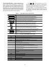
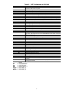
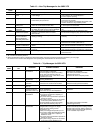
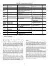
Table 20 — Alarms Displayed at Unit LID
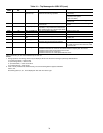
NOTES:
1. Unit display will indicate alarm by displaying “There is 1 Alarm” or
“There are X alarms”, for the active alarms in the controller.
2. Red light on, indicating alarm.
3. Yellow light is on, indicating a warning.
Standard Diagnostic Features, Alarm and
Warning Lights
SUPPLY AIR TEMPERATURE SENSOR FAILURE — If
the supply air temperature sensor fails and indicates either
245 F from a short or -40.0 F from and open sensor the control-
ler outputs will be forced to off with safety forces, the alarm
output will close and the red Alarm light will be lit. A system
alarm will be generated and displayed on the unit keypad. Unit
reset is automatic when the supply air sensor has a valid
reading again.
DUCT STATIC PRESSURE SENSOR FAILURE — If the
duct static pressure sensor fails and indicates either 5.0 inches
from a short or 0.0 inches from and open sensor the controller
outputs will be forced to off with safety forces, the alarm
output will close and the red Alarm light will be lit. A system
alarm will be generated and displayed on the unit keypad. Unit
reset is automatic when the supply air sensor has a valid
reading again.
FIRE/SHUTDOWN INPUT (FSD) — This is a normally
closed input, which when opened, deenergizes an isolation
relay in the unit, opening the input to the controller. When this
input turns opens, all control outputs are immediately turned
off, including the fan. Fire forces will be displayed on the
outputs. Unit reset is automatic when the FSD input is closed
again. A system alarm will be generated and displayed at the
keypad.
DUCT HIGH STATIC INPUT (DHS) — This air switch
provides over pressurization protection for the ductwork. It is
factory installed in the unit. The switch is a normally open
switch, with adjustable manual setting (range is 1 to 5 in. wg
default setting is 3.0 in. wg). Upon switch closure, the control-
ler outputs will be forced to off with safety forces, the alarm
output will close and the red Alarm light will be lit. A system
alarm will be generated and displayed on the unit keypad. Unit
reset is automatic when the duct pressure is again below the
switch setting minus the device hysteresis.
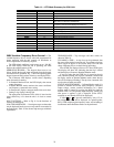
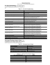
COMPRESSOR MULTIPLEX (MUX) BOARD — A re-
sistance board is used to generate a variable voltage input to the
controller to determine compressor status. If the voltage output
from this board gets out of the acceptable range the controller
outputs will be forced to off with safety forces, the alarm
output will close and the red Alarm light will be lit. A system
alarm will be generated and displayed on the unit keypad. Unit
reset is automatic when the Mux board has a valid reading
again. The valid range is between 1.5 and 10 vdc. The table
below indicates what voltages correspond to the compressor
status indicated in the controller.
FUNCTION ALARM MESSAGE (Actual Text) CAUSE UNIT RESPONSE (See Notes) RESET
SAT
SATxx.xdFoutside
limit of xxx.x dF
SAT reads out of prescribed range
for 5 sec. during operation
Unit shuts down and
indicates alarm
Automatic
DSP_ALM
Duct Static Sensor Failure Duct Pressure Sensor reading is out of
range (i.e., likely faulty sensor or circuit).
Unit shuts down, indicates alarm Automatic
FSD Fire Shutdown External Fire Alarm input opens for 5 sec. Unit shuts down, indicates alarm Automatic
DHS
Duct High Static Pressure Pressure rises above 3.0 in.H2O during
operation. Set point adjustable on the switch.
Used for Off position of switch on smaller
units with one controller
Unit shuts down, indicates alarm Automatic
CSMUX
CSMUX x.xx Volts outside
limit of x.xx Volts
Compressor safety circuit Resistor Board
reads out of prescribed range for 5 sec.
during operation
Unit shuts down and indicates
alarm
Automatic
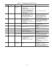
CDWF
Check Condenser Water Flow Waterflow Switch contacts are open at startup,
or go open for 5 sec. during operation.
Compressor Cooling shuts down,
locks out and indicates warning
Automatic
FLTS
Change Filters Filter pressure drop exceeds Filter Pressure
Switch setting (and contacts open) for 5 sec.
Unit operates normally,
but still indicates Warning
Automatic
FREEZ
Economizer Freeze Condition Economizer Freeze Switch contacts for 5 sec.
open during operation.
Warning indicated for 15 minutes
turns off ventilation request, then
unit shuts down and Econo valve
opens, pump request stays on,
and Alarm indicated
Automatic
C1_ALM
C2_ALM
C3_ALM
C4_ALM
Compressor 1 Fault
Compressor 2 Fault
Compressor 3 Fault
Compressor 4 Fault
Compressor safety circuit opens for 2 sec. Unit shuts that compressor down,
and indicates Warning, but retries
2 more times before locking it out.
Automatic
SFS
Check Supply Fan Duct Pressure Sensor reading is below .3 in.
H2O at 10 sec. after starting fan, or during
operation, or
reads above .3″ when fan is
supposed to be Off.
If on but indicates off cooling,
and heating will be disabled
warning light will be on
Automatic
EWT
EWT xx.x dF outside
limit of xxx.x dF
EWT reads out of prescribed range for 5 sec.
or more
Indicates warning Automatic
MA_RA
MA_RA xx.x dF outside
limit of xxx.x dF
ma_ra reads out of prescribed range for 5 sec.
or more
Indicates warning Automatic
PHASE
Phase Loss Phase monitor activates (see “Phase
Loss/Reversal Protection Switch” on page 5)
for 5 sec. during operation.
Unit shuts down, indicates alarm Automatic
BYPAS
BYPAS switch in Bypass position or Off,
local remote in Off position