18
Units not equipped with a water economizer can be ordered
with the reverse/head pressure control valve factory installed
and a pressure transducer located in the discharge line of
compressor no. 1.
When the condenser water temperature gets low enough to
cause the head pressure to drop, the valve will be modulated to
control the head pressure of all four compressors by varying
the water flow through the condensers.
When the unit is operating and the COOLOK software
point is enabled and the EWT gets below 60 F, the Head
software point will become enabled and the head pressure
control valve will modulate to keep the head pressure at the
head pressure set point (SETPT04). The default set point is
225 PSI and may be set from 200 to 250 PSI. The minimum
output value for the head pressure control algorithm is 40% in
order to maintain a minimum flow through the condensers. The
valve will modulate between 40 and 100%. Do not set the
minimum lower than 40% or the compressors may shut down
due to low flow, resulting in the high-pressure switch tripping.
VENTILATION REQUEST (50XJ) — The ventilation request
output will close a set of relay contacts to activate a ventilation
damper whenever the supply fan and supply fan status are both
true and the TIMECLOCK software point is on.
VAV TERMINAL OPERATION OUTPUT (50XJ) — The
VAV terminal control output (TRMCT) closes a set of relay
contacts to indicate to non-Carrier air terminals that the fan is
either forced on or is going to turn on. This signals the
terminals to open and start controlling to the desired CFM and
Temperature set points.
VAV TERMINAL OPEN OUTPUT (50XJ) — The VAV ter-
minal open output (TRMOP) closes a set of relay contacts to
command the air terminals to open to maximum CFM at times
when the fan is operating on the VFD Bypass.
PUMP AND TOWER OUTPUTS (50XJ) — The pump and
Tower outputs close a set of relay contacts to indicate that the
50XJ unit is in operation and may require condenser water
flow through the unit.
BUILDING PRESSURE CONTROL (50XJ) — The building
pressure control output provides an analog 4 to 20 mA signal to
control return fan or exhaust fan speed. Fan speed is modulated
to maintain the building static pressure set point (SETPT07).
The control parameters for the building pressure set point
and building pressure are read and controlled in milliamps but
are converted to inches of water for ease of setting and display.
The range and low start values of the sensor selected should be
configured in the custom configurations screen. The raw sensor
value in milliamps will be displayed on the hardware point
BSP. The converted sensor reading in inches of H
2
Owillbe
displayed at the software point BSP_IN. The set point input in
SETPT07 in inches of H
2
O is converted to a raw milliamp set
point in SETPT08. The algorithm controls to the milliamp
values since the math required for control using the static
pressure in inches generates numbers too small to be used
given the range of the controller configuration parameters.
Diagnostic Features — The CC6400 provides a number
of features to help protect the unit and allow problem
diagnosis.
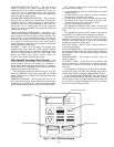
CRITICAL FAULT — The controller provides an output
(for field connection) to signal an external building systems
monitor or control that the unit is not operating properly and
has shut down. A red light mounted on the front of the unit
provides visual indication of this alarm condition.
NOTE: If the Local/Off/Remote switch is in the OFF
position, it is normal for the red alarm light on the display
panel to be lit, indicating that the unit is disabled.
NON-CRITICAL FAULT — The controller provides an
output for a yellow light, mounted on the front of the unit, that
indicates the need for minor maintenance or service.
FIRE INPUT (FSD) — This is a normally closed input, which
when opened, deenergizes an isolation relay in the unit, opening
the input to the controller. When this input turns On, all control
outputs are immediately turned Off, including the fan. Unit
reset requires manual resetting at the main controller keypad.
DUCT HIGH STATIC INPUT (DHS) — This air switch
provides backup protection for the ductwork. It is factory
installed in the unit, wired to the unit main controller to receive
5 vdc. It is a normally open discreet switch, with adjustable
manual setting at the switch (range is 1 to 5 in. wg). Upon
switch closure, the controller immediately turns all outputs Off,
including fan, and then indicates an alarm both by turning On
its Alarm Output, Red Alarm light and via communications.
DIRTYFILTERSSWITCH(DFLTS)(50XJ)—Thisswitch
measures the change (delta) in air pressure across the filters.
When the delta increases beyond the preset setting, a yellow
warning light will be lit, indicating that the filters need cleaning
or replacement.
The switch receives 5 vdc from the unit controller and
monitors air pressure delta across the return air filters. Switch is
normally open, with manually adjustable setting at the switch
between 0.5 and 1.5 in. wg. Upon closure, controller should
wait to assure closure for minimum 1 minute, then indicate an
alert via its non-critical alert output and via communications.
All other unit operation should remain normal.
COMPRESSOR OVERLOAD (COL)/SAFETIES — Each
compressor circuit is provided with a temperature overload
board (Copeland Protector Bd.), a Current Overload/Sensor
Board (COL), High Pressure Switch (HPS), Low Pressure
Switch (LPS), and Evaporator Freeze Switch (EFS). These
devices are wired in series to the contactor for each compressor.
Each such circuit is then wired through a common resistor board;
such that any one or more input(s) to the main controller allows it
to discern which compressor is not operating when it should be.
The Current Overload Board (COL) is located in the unit
control box, wired in the control power line for the compressor
pilot relay (which drives the compressor contactor), and
incorporates a current loop which monitors one leg of the
compressor power leads. This board is powered along with the
related compressor contactor.
Whenever the compressor current falls below a threshold
level (i.e., compressor not operating), it activates an on-board
relay which opens power to the compressor pilot relay (i.e.,
compressor contactor), and turns On a control power feedback
line to the unit controller, via the resistor board (described
above). Any one of the safety switches described herein will
cause this event. In the event this occurs, the controller shall
turn OFF this compressor, and start the next compressor in
sequence. After a 5-minute period, the controller shall restart
this compressor, and turn the other one off, as cooling demand
requires. If the ‘problem’ compressor then operates for 10 min-
utes of run time normally, the unit reverts to normal operation
and compressor sequencing. If not, and the same error occurs
again, this compressor shall be shut down and replaced with
the next compressor, as before, and held off for 10 minutes. It
shall then be restarted and the other compressor shut down, as
before. If it does not run successfully for 10 minutes of normal
run time again, it is shut down and replaced a third time. This
time it is held off for 15 minutes. If the “problem” compressor
does not operate successfully for the 10 minutes of normal run
time this third time, this compressor ONLY is shut down and
locked out for servicing. Alarm output (Red light) flashes and
then remains on.
HIGH-PRESSURE SWITCH (HPS) — This switch is located
in the discharge refrigerant line of each compressor, and is set
to open at pressures above 360 psig. It is wired in the 115 vac
control power line of the compressor contactor (in series with
the LPS and EFS), and activates the COL board (above) when
it opens.


