


24
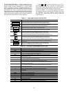
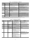
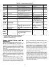
Table 15 — Non-Trip Messages for the 50BV VFD
NOTES:
1. ST : Terminal of stand by function.
2. When the ON/OFF function is selected for DC braking (DB), using the input terminal selection parameter, you can judge
the inverter to be normal if “db” disappears when opening the circuit between the terminal and CC.
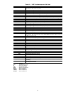
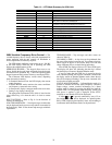
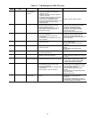
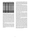
Table 16 — Trip Messages for 50BV VFD
ERROR
CODE
PROBLEM POSSIBLE CAUSES REMEDIES
OFF (Note 1) ST terminal OFF • The ST-CC circuit is opened. • Close the ST-CC circuit.
NOFF Undervoltage in main
circuit
• The supply voltage between R, S and T is
under voltage.
• Measure the main circuit supply voltage.
If the voltage is at a normal level, the
inverter requires repairing.
rtrY Retry in process • The inverter is in the process of retry.
• A momentary stop occurred.
• The inverter is normal if it restarts after
several tens of seconds.
The inverter restarts automatically. Be careful ofthe
machine because it may suddenly restart.
Err1 Frequency point
setting error
• The frequency setting signals at points 1
and 2 are set too close to each other.
• Set the frequency setting signals at points
1 and 2 apart from each other.
CLr Clear command
acceptable
• This message is displayed when pressing
the STOP key while an error code is displayed.
• Press the STOP key again to clear the
trip.
EOFF Emergency stop
command acceptable
• The operation panel is used to stop the
operation in automatic control or remote
control mode.
• Press the STOP key for an emergency stop.
To cancel the emergency stop, press any other key.
HI/LO Setting error alarm /
An error code and
data are displayed
alternately twice each.
• An error is found in a setting when data is
reading or writing.
• Check whether the setting is made
correctly.
db DC braking • DC braking in process • Normal if the message disappears after
several tens of seconds. (See Note 2.)
In It Parameters in the
process of initialization
• Parameters are being initialized to default
values.
• Normal if the message disappears after a
while (several seconds to several tens of seconds).
Setup parameters in
the process of being set
• Setup parameters are in the process of
being set.
• Normal if the message disappears after a
while (several seconds to several tens of seconds).
Atn Auto-tuning in process • Auto-tuning is in process. • Normal if the message disappears after
several seconds.
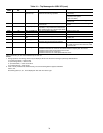
ERROR
CODE
COMMUNICATION
NO.
PROBLEM POSSIBLE CAUSES REMEDIES
OC1 1 Overcurrent during
acceleration
• The acceleration time ACC is too short.
• The V/F setting is improper.
• A restart signal is input to the rotating
motor after a momentary stop, etc.
• A special motor (e.g. motor with a small
impedance) is used.
• Increase the acceleration time ACC.
• Check the V/F parameter.
• Use F301 (auto-restart) and F302
(ride-through control).
• Increase the carrier frequency F300.
OC2 2 Overcurrent during
deceleration
• The deceleration time dEC is too short.
(During deceleration)
• Increase the deceleration time dEC.
OC3 3 Overcurrent during
operation
• The load fluctuates abruptly.
• The load is in an abnormal condition.
• Reduce the load fluctuation.
• Check the load (operated machine).
OCR 5 Arm overcurrent at
start-up
• A main circuit element is defective. • Make a service call.
OCL 4 Overcurrent (An
overcurrent on the
load side at start-up)
• The insulation of the output main circuit or
motor is defective.
• The motor has too small impedance.
• Check the cables and wires for defective
insulation.
OP1 A Overvoltage during
acceleration
• The input voltage fluctuates abnormally.
(1) The power supply has a capacity of
200kVA or more.
(2) A power factor improvement capacitor is
opened or closed.
(3) A system using a thyristor is connected
to the same power distribution line.
• A restart signal is input to the rotating
motor after a momentary stop, etc.
• Insert a suitable input reactor.
• Use F301 (auto-restart) and F302
(ride-through control).
OP2 B Overvoltage during
deceleration
• The deceleration time dEC is too short.
(Regenerative energy is too large.)
• F304 (dynamic braking resistor
activation) is off.
• F305 (overvoltage limit operation) is off.
(1) The input voltage fluctuates abnormally.
The power supply has a capacity of
200kVA or more.
(2) A power factor improvement capacitor is
opened or closed.
(3) A system using a thyristor is connected
to the same power distribution line.
• Increase the deceleration time dEC.
• Install a suitable dynamic braking resistor.
• Enable F304 (dynamic braking selection).
• Enable F305 (overvoltage limit operation).
• Insert a suitable input reactor.