


42
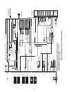
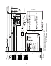
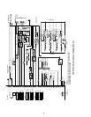
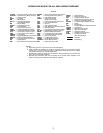
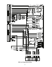
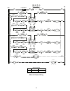
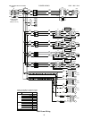
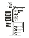
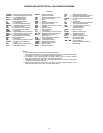
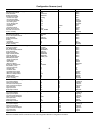
LEGEND AND NOTES FOR ALL 50XJ WIRING DIAGRAMS
LEGEND
ALARM — Unit Alarm Relay (Critical Fault)
ALM-CM— Alarm/Warning Relay Common
BPS_S — Fan Start/Stop Relay
(VFD Bypass Mode)
BYPAS — VFD Bypass Control
C—Compressor Contactor
CB — Circuit Breaker
CDWF — Condenser Waterflow Relay
CDWFS — Condenser Waterflow Switch
CH — Crankcase Heater
CLO — Compressor Lockout Control
CMP — Compressor Control Relay
COMP — Compressor
CSMUX — Signal Multiplexer-Comp Status
CUVL — UVC Light For Indoor Coil Area
DEHUM — External Dehumidification
DHS — Duct High Static Limit Switch
DISC1 — Disconnect Switch
DS — Door Switch
DSP — Duct Static Pressure Transducer
ECONO — Economizer Valve/Damper
Control
EWT — Entering Water Temp. Sensor
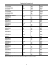
FLTS — Filter Status Switch
FREEZ — Freeze Thermostat
(Water Economizer)
FRZ — Freeze Thermostat (DX Circuit)
FSD — Fire Alarm/Shutdown
FU — Fuse
GND — Ground
HEAT — Electric Heat Stage Control
HIR — Heat Interlock Relay
HPS — High Refrigerant Pressure Switch
HRN — Harness
HWV — Hot Water Valve
IFM — Indoor Fan Motor
J—Jumper Wire
LPS — Low Refrigerant Pressure Switch
MA_RA— Mixed/Return Air Temp. Sensor
MVLV — Modulating Valve (Econ)/
Heat Pres. Ctl.
OLR — Compressor Motor Protector
PCB1 — Unit Control Board
PCB2,3— I/O Expansion Board
PHASE— Phase/Rotation Monitor
PUMP — Water Pump Request
RESET — External Reset
ROCC — Remote Occupancy
SAT — Supply Air Temp. Sensor
SPT — Space/Zone Temperature Sensor
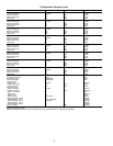
SF — Supply Fan Start/Stop Relay
SPEED — 0-10 VDC Signal Isolator for VFD
SW — Switch
T—Transformer
TB1 — Power Distribution Terminal Bloc
k
TB2 — 120 V-Hot Terminal Block
TB3 — 120 V-Neutral Terminal Block
TB5-7 — Terminal Blocks for
Field Connections
TOWE
R
—
Tower Request
TRMCT — VAV Terminals Control
TRMOP — VAV Terminals Open
VENTR — Ventilation Output
VFD — Variable Frequency Drive
WARN — Unit Warning Relay
(Non-Critical Fault)
Optional Wiring
(Optional Items Noted With “*”)
—— Field Wiring
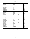
NOTES:
1. Partial wiring shown on both power and control diagrams.
2. All class 2 transformers are wired into separate circuits. Do not interconnect these
transformers or circuits; circuit separation shall be maintained.
3. On 200/240 v units, the transformers are factory wired for 240 v. For 200 v applica-
tions, move the blue wire to the 200 v tap of each transformer.
4. Shielded wire shall have drain wire connected to VFD ground screw. The floating end
of the drain wire shall be insulated.
5. Shielded wire shall have drain wire connected to the control panel, adjacent to the
PCB. The floating end of the drain wire shall be insulated.