


19
LOW-PRESSURE SWITCH (LPS) — The Low-Pressure
Switch is located in the suction refrigerant line of each
compressor, and is set to open at pressures below 27 psig. It is
wired in the 115 vac control power line of the compressor
contactor (in series with the HPS and EFS), and activates the
COL board (above) when it opens.
EVAPORATOR FREEZE SWITCH (EFS) — This is a thermal
disk type switch, mounted on a return bend of the evaporator,
refrigerant circuit for which corresponds to each respective
compressor, and is set to open at temperatures below 28 F. It is
wired in the 115 vac control power line of the compressor
contactor (in series with the HPS, and activates the COL board
(above) when it opens.
COPELAND PROTECTOR BOARD — This board is pro-
vided with each compressor, installed in the terminal box, since
these compressors do not have internal current protection. This
board activates at an overtemperature setting, and locks out
operation of the compressor for 30 minutes; there is no method
to over-ride or reset this timer. Due to this timing function,
please note that the compressor will not attempt to restart until
the third attempt described above.
ALARMS — Alarms can be provided via 4 methods; Unit
mounted Alarm Light (Red and Yellow), Keypad Display,
Network Communications, or a discreet Alarm Output to the
Field Low Voltage Terminal Strip. This field output circuit
includes an isolation relay and dry contacts. Alarms are
covered in detail in the Troubleshooting section.
50XJ Variable Frequency Drive Control — The
variable frequency drive is factory wired and programmed for
proper operation with the unit controls; no installation or
service adjustments are normally required. There is an interface
display for the VFD, independent of the main control display,
mounted on the front of the 50XJ unit.
The VFD default conditions at unit power up are: “AUTO”
run mode, “REMOTE” speed control, and “OFF” in the LED
display. When the fan is operating, the LED displays the output
frequency in Hz.
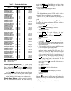
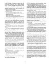
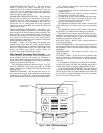
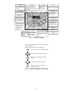
OPERATING KEYPAD — The keypad allows users to en-
able or disable the keypad, input commands from the keypad,
and monitor drive operation. Fig. 6 shows the operating panel
keypad layout and the locations of the keys and display LEDs.
The 7-character LED displays various values, depending
upon what mode is running.
• In Standard Monitor mode: the LED displays the current
output frequency.
• In Status Monitor mode: monitors the status conditions
and frequency command value setting.
• In Setup mode: displays setup parameter titles and values.
• In Program mode: displays parameter group titles, indi-
vidual parameter names, and parameter values.
• During a trip: displays the trip title.
The appropriate local/remote LED, which is inset into the
speed control key, is lit when the unit is in Local or Remote
mode.
The appropriate manual/auto LED, which is inset into the
run mode key, is lit when the unit is Manual or Auto mode.
When numeric data is shown on the LED display, the corre-
sponding unit indication LED will be lit. If no unit indication
LED is lit, the current data has no unit or the corresponding
unit does not exist on the display panel.
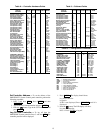
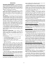
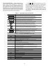
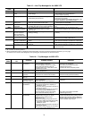
KEY FUNCTIONS — Refer to Table 11 for the functions of
each key on the keypad.
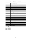
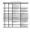
NON-TRIP MESSAGES — Non-trip messages are those that
may be displayed but do not cause a trip and are not recorded in
the fault history. Table 12 lists the non-trip messages with their
explanations.
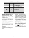
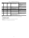
TRIP MESSAGES — Trip messages and their causes are
shown in Table 13.
CLEARING A TRIP — A trip clear can be performed after
the cause of the trip has been removed. To perform a trip clear,
either switch off power to the inverter or use the following
procedure:
Press Stop/Reset. The display will show: CLr. Press Stop/Re-
set again. The display will show: 0.0, indicating that the trip is
cleared and the display will return to Standard Monitor mode.
If any key other than the STOP/RESET key is pressed at the
trip clear command prompt, the trip clear command is aborted
and the display returns to Standard Monitor mode (where the
trip title will be displayed flashing).The trip clear command
does not clear the recorded past faults.
LOCAL/REMOTE
SPEED CTRL
MANUAL/AUTO
RUN MODE
HZ
PERCENT
SECONDS
KW/AMPS/VOLTS
SETUP
PROGRAM
MONITOR
READ
WRITE
RUN
STOP
RESET
KEYS (TYPICAL8)
MANUAL/AUTO LEDS
LOCAL/REMOTE LEDS
7-CHARACTER LED
DISPLAYAREA
UNITS LED (TYPICAL4)
Fig. 6 — 50XJ VFD Display Keypad