


2
Comfort Controller I/O Module (PCB2) — This
input/output module is factory installed in the 50XJ unit and
allows additional field points (8 inputs and 8 outputs): VFD
(variable frequency drive) Bypass, VAV Terminals Control,
Building Ventilation, and Heating Interlock.
Comfort Controller I/O Module (PCB3) — This
accessory control input/output module can be ordered separate-
ly and field-installed in the 50XJ unit. This module allows the
addition of the following field-installed sensors: Tower Sump
Temperature Sensor, Leaving Water Temperature Sensor,
Building Pressure Sensor, CO
2
Sensor, Indoor Relative
Humidity Sensor, and Outdoor Temperature Sensor.
The accessory I/O module provides the following control
outputs (relays): 4-stage heat control, water pump request, tower
request, modulating exhaust fan, and external dehumidification.
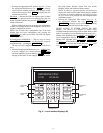
Local Interface Display — The Local Interface Display
(LID) is mounted on the front of the 50BV,XJ units. A number
of user-adjustable features are entered/changed using the
display keypad. These features described in detail in the Using
the Local Interface Display section of this manual.
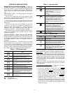
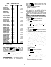
PCB Addresses — Switch 1 (SW1) is used to set each
controller’s address. Individual DIP switches on each board are
used to set the addresses for individual hardware points. PCB1
switches are factory-set for hardware points 1-15, PCB2 DIP
switches are set for points 17-32, and PCB3 for points 33-48.
For more information, refer to Table 1 and the Optional and
Field-Installed Accessory Sensors/Devices section.
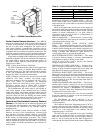
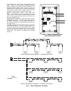
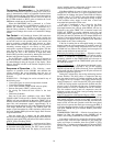
Control Module Communication — When power is
applied to the OMNIZONE™ System Control panel, the red
LED (light-emitting diode) on the top front of the processor
module will flash at a rapid pace (about twice a second) for the
first 30 to 60 seconds. See Fig. 1. This rapid flash will then be
replaced by a slower paced flash (about once per second).
The green LED below the red LED will start flashing. This
LED indicates input/output communications for accessory input
output modules and the LID.
The yellow LED (the third LED from the bottom of the con-
troller [PCB1]) will flash when the controller is broadcasting
CCN messages to a laptop or other computer.