


20
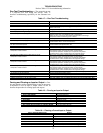
STATUS MONITOR MODE — In Status Monitor mode, it is
possible to monitor the VFD status (frequency command, output
voltage, current, terminal information, etc.). Status monitor
mode is entered by pressing the Setup/Program/Monitor key,
then selecting MON at the mode selection menu and pressing
the Read/Write key. Table 11 details the procedure for entering
status monitor mode (from standard monitor mode) and viewing
all the monitored status variables. The present output frequency
(which, just after power is applied, is 0.0) is displayed. (If the ST-
CC terminals are not shorted, OFF will be displayed).
If either or is pressed continuously, every 0.5 sec
the next/previous item will be displayed. As optional points,
RUN, STOP, displaying the frequency status, and switching to
local/remote and manual/auto modes can be performed.
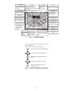
MANUAL MODE — To override the automatic unit controls
and manually operate the fan from the VFD display, press keys
for “MANUAL” run mode, “LOCAL” speed control, and
press the Up or Down arrow keys to increase or decrease
output frequency.
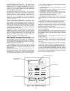
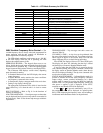
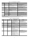
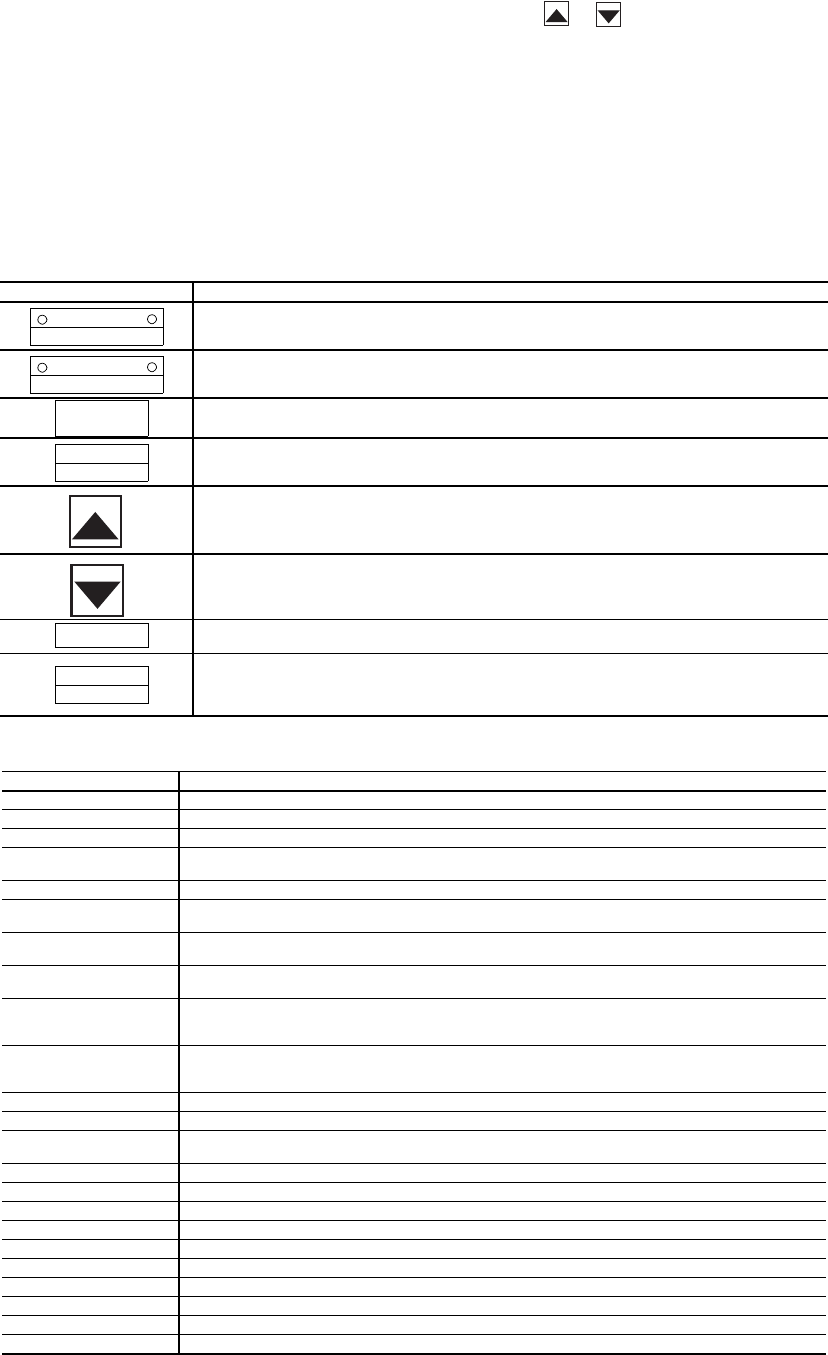
Table 11 — Keys and Functions for 50XJ VFD
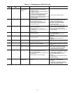
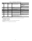
Table 12 — VFD Non-Trip Messages for 50XJ Unit
KEY FUNCTION
Local/Remote Key
Switches the source of frequency command information from panel/terminal
block. The appropriate LED is lit to indicate local or remote frequency command.
Manual/Auto Key
Switches the source of run/stopcommand information from panel/terminal block.
The appropriate LED is lit to indicate manual or auto run/stop command.
Setup/Program/Monitor Key
Toggles between Setup, Program, Monitor, and Frequency Mode.
Read/Write Key
Mode, group, parameter, data, and frequency selection key. This key is used to
select or enter a parameter value, a frequency command, or a group name.
Up Key
Scrolls up the setting of the currently displayed parameter. If the key is held
down, the scrolling speed gradually increases. Only RAM values are changed.
Also toggles to other function group entries. Pushing Read/Write key saves the setting.
Down Key
Scrolls down the setting of the currently displayed parameter. If the key is held
down, the scrolling speed gradually increases. Only RAM values are changed.
Also toggles to other function group entries. Pushing Read/Write key saves the setting.
Run Key
This key is used to start a RUN command (only valid when in manual control mode).
Stop/Reset Key
Functionsas the STOPkeyand emergency stop keyduring local operation.
Functions as the RESET key when an inverter trip occurs. In all other modes,
emergency off is engaged when this key is pressed twice.
LED MESSAGE EXPLANATION
OFF Displayed whenever the ST-CC connection is open.
pOFF Displayed when the VFD control power supply voltage is too low.
nOFF Displayed when the VFD’s main DC bus voltage is low.
rtrY Auto-restart message: alternately displayed with the output frequency whenever the
VFD tries to automatically restart after a non-critical trip.
Err1 Displayed when 2 frequency points (F-P1,F-P2,etc.) are set too close to each other.
CLr Displayed during a pending clear command (after the STOP/RESET key has been
pressed ONCE after a trip).
EOFF Displayed during a pending emergency off command (after the STOP/RESET key has
been pressed ONCE when in terminal control mode).
CtrL Displayed during a pending coast stop command (after the Local/Remote key has
beenpressed oncewhen in localcontrol mode while the VFD is running).
HI This maximum value warning message “HI” will be alternately displayed in the data
field of a parameter when an attempt is made to increase the setting value greater than
the parameter’s maximum value.
LO This minimum value warning message “LO” will be alternately displayed in the data
field of a parameter when an attempt is made to decrease the setting value less than
the parameter’sminimum value.
PASS Displayed if the correct password is entered at the password prompt.
Err Displayed if an incorrect password is entered at the password prompt.
E1 Displayed when the VFD attempts to display a number that exceeds four
numerical digits.
db Displayed when DC injection braking is being executed.
dbon Displayed when motor shaft stationary control is being executed.
FJOG Displayed when in forward JOG mode.
rJOG Displayed when in reverse JOG mode.
L VFD/motor overloadpre-alarm display.
C Overcurrent pre-alarm display.
P Overvoltage pre-alarm display.
H Overheat pre-alarm display.
t Option board communication alarm display.
InIt Displayed when the VFD is initializing values during resetting/power-up.
LOCAL/REMOTE
SPEED CTRL
MANUAL/AUTO
RUN MODE
SETUP
PROGRAM
MONITOR
READ
WRITE
RUN
STOP
RESET