


4
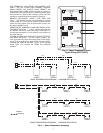
Carrier Comfort Network Interface — The 50BV,XJ
units can be connected to the CCN (Carrier Comfort Network)
if desired. System elements are connected to the communica-
tion bus in a daisy chain arrangement. The negative pin of
each system element’s communication connector must be
wired to the respective negative pins, and positive pins on each
component must be connected to respective positive pins. The
controller signal pins must be wired to the signal ground pins.
Wiring connections for CCN must be made at the 3-pin plug.
At any baud rate (9600, 19200, 38400 baud), the number of
controllers is limited to 239 devices maximum. Bus length may
not exceed 4000 ft, with no more than 60 total devices on
any 1000-ft section. Optically isolated RS-485 repeaters are
required every 1000 ft.
NOTE: Carrier device default is 9600 baud.
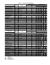
The CCN Communication Bus wiring is field-supplied and
field-installed. It consists of shielded three-conductor cable
with drain (ground) wire. The cable selected must be identical
to the CCN Communication Bus wire used for the entire
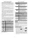
network. See Table 2 for cable recommendations.
NOTE: Conductors and drain wire must be at least 20 AWG
(American Wire Gage), stranded, and tinned copper.
Individual conductors must be insulated with PVC, PVC/
nylon, vinyl, Teflon, or polyethylene. An aluminum/
polyester 100% foil shield and an outer jacket of PVC,
PVC/nylon, chrome vinyl, or Teflon with a minimum
operating temperature range of –20 C to 60 C is required.
The communication bus shields must be tied together at
each system element. If the communication bus is entirely
within one building, the resulting continuous shield must be
connected to ground at only one single point. If the communi-
cation bus cable exits from one building and enters another
building, the shields must be connected to the grounds at a
lightning suppressor in each building (one point only).
Optional and Field-Installed Accessory Sensors/
Devices —
The 50XJ unit can be ordered with options and
accessories that add functionality and control. These options
and accessories are controlled by the CC6400 system as
described below.
NOTE: The CC6400 Control software includes all PCB1
functions, and most of the sensors/devices associated with
those functions are factory installed. However, some PCB1
sensors/devices must be field-connected to the proper terminal.
PCB2 devices are field-installed accessories. The CC6400
software includes these functions, but the actual sensor/device
must be installed and wired in the field. PCB3 is an accessory
control module. All PCB3 sensors/devices and software are
field-installed.
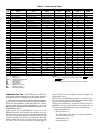
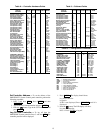
Table 2 — Communication Cable Recommendations
REMOTE OCCUPANCY CONTROL (PCB1) — This con-
trol is a field located switch, controller or timer input which,
when activated, tells system when to switch from Unoccupied
to Occupied mode.
When in Occupied mode, the unit turns on the supply fan
and controls supply fan speed to maintain a duct static set point
measured at the Duct Static Pressure Sensor (DSP). The unit
operates to provide conditioning to a set point. When in
Unoccupied mode, the unit provides no cooling/heating, or
controls to a ‘setback’ set point.
FIRE ALARM (PCB1) — The fire alarm is a control voltage
input to the 50XJ unit, which causes the controller to shut the
system down in the event of a fire.
CONDENSER WATER FLOW SWITCH (50XJ
PCB1) — This thermal dispersion type flow switch if factory
installed, is located in the unit waterline to ensure that there is
waterflow before allowing the unit to start the compressor(s). If
no flow is detected, then compressor operation and economizer
cooling is avoided until waterflow is again detected. An
warning light (yellow) is provided during this state.
HEAT INTERLOCK OUTPUT (50XJ PCB2) — This output
is activated whenever heating is activated, commanding the
VAV dampers to operate in heating control mode.
NOTE: In order to this output to function, the Terminal
Occupied output must also be on.
TERMINAL OCCUPIED (50XJ PCB2) — Terminal Occu-
pied is activated to command VAV dampers to control to the
cooling set point. Terminal Occupied must be on along with
Heat Interlock for heating set point control to function.
EXTERNAL RESET INPUT (50XJ PCB2) — This modu-
lating input (0 to 10 vdc) allows remote adjustment (upward) of
the Supply Air Temperature (SAT) sensor set point. The default
External Reset Input setting is 55 F. This variable input can
raise the set point by up to 20 F for a full-range input signal, or
to any point in between.
WATER ECONOMIZER COIL (50XJ PCB2) — This factory-
installed option contains a water-to-air coil, two (2) electronic
motorized water valves, and related piping. Control of the water
economizer also requires a Mixed/Return Air Temperature
Sensor, a Condenser Water Inlet Temperature Sensor and an
Economizer Freezestat safety switch.
The electronic motorized water valves are each controlled
by the unit controller via separate 4 to 20 mA variable signals
to define variable valve position.
The Mixed/Return Air Sensor (MA_RA) is an air
temperature sensor located in the unit, between economizer
coil and evaporator.
The Condenser Water Inlet Temperature Sensor (CWT) is
located at the unit water inlet connection. This sensor receives
input power from the unit main controller and provides a linear
variable 1 to 5 vdc signal back to the controller. The full
temperature range is 32 to120 F.
The 50XJ units can be connected to two types of building
water systems: variable and fixed or constant flow control. In
either case, the economizer water valves are opened whenever
there is a call for Cooling and the Inlet Water Temperature is
colder than the Econ Start Set Point in the custom configuration.
MANUFACTURER PART NUMBER
Alpha 2413 or 5463
American A22503
Belden 8772
Columbia 02525
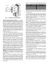
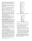
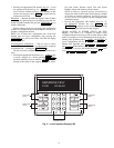
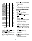
RED
GREEN
(IO BUS
COMMUNICATIONS)
YELLOW
(CNN BUS
COMMUNICATIONS)
(POWER)
Fig. 1 — CC6400 Control Module LEDs
STATUS