


21
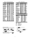
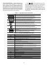
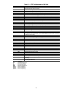
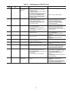
Table13—VFDTripMessagesfor50XJUnit
LEGEND
LED MESSAGE EXPLANATION
nErr Displayed in the trip history in standard monitor mode when no trip has been recorded
since the last VFD reset or trip clear.
OC1 Overcurrent during acceleration trip
OC2 Overcurrent during deceleration trip
OC3 Overcurrent during normal (constant speed) run trip
OC1P Overcurrent in DC section during acceleration trip
OC2P Overcurrent in DC section during deceleration trip
OC3P Overcurrent in DC section during normal (constant speed) run trip
OCL Load end over current trip detected at start-up (output terminals, motor wiring, etc.)
OCA1 U-phase short circuit trip detected at start-up
OCA2 V-phase short circuit trip detected at start-up
OCA3 W-phase short circuit trip detected at start-up
OP1 Overvoltage during acceleration trip
OP2 Overvoltage during deceleration trip
OP3 Overvoltage during normal (constant speed) run trip
OLIn VFD overloaded trip
OLnt Motor overloaded trip
OCr Dynamic braking resistor overcurrent trip
OLr Dynamic braking resistor overload trip
OH Inverter overheat trip
E Emergency off trip message. Displayed after the STOP/RESET key has been pressed
once when in Auto Control mode, or press STOP/RESET key twice within one second
in Manual control mode.
EEP1 EEPROM failure during write cycle
EEP2 EEPROM abnormality during initial reading
Err2 RAM error
Err3 ROM error
Err4 CPU error
Err5 Communication interruption error
Err6 Gate array error
Err7 Output current detection circuit error
Err8 Option PCB error trip
Err9 Option ROM error
UC Low operating current trip
UP1 Main circuit undervoltage trip
Ot Overtorque trip
EF1 Software detected earth fault trip
EF2 Hardware detected earth fault trip
Etn Auto-tuning error
EtYP Inverter typeform and EEPROM typeform mismatch error
dANP Damper trip. When damper function is selected, and damper is closed while the motor
is running.
LOSS IV analog input loss. Valid when LA15 = 3 and frequency command is selected from
IV analog input terminal.
CPU — Central Processing Unit
IV — Analog Input Terminal
PCB — Printed Circuit Board
RAM — Random Access Memory
ROM — Read-Only Memory
U-phase — Phase 1 Output (T1)
V-phase — Phase 2 Output (T2)
W-phase — Phase 3 Output (T3)