


13
8. Enter the last two digits of the current year. Press
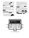
then press . The LID display will show:
Update Clock
No
9. Press 1 and then to cause the controller to
update the clock. The LID display will flash. Press
twice to view the default display and the clock
should update to the input time and date.
Configure Schedules — Schedules are one method of
starting and stopping the unit at specified intervals. To config-
ure the schedules, perform the following procedure:
1. Press 1 and then . The LID display will show:
Occupancy Algorithm
2. Press . The LID display will show:
Time Schedule
Enter to select
3. Press . If the LID display shows “MODE 0” then
the user is in Maintenance mode and the LID display is
showing the maintenance information for the occupancy
schedule. Press to enter the configuration
mode. The LID display will show:
Manual Override Hours
0 hours
This is the first configuration for each occupancy
algorithm and is used to put the schedule in or out of
occupancy override for the number of hours entered.
4. Press . The LID display will show:
Period 1: Day of week
00000000
The eight digits represent if this period should apply to
certain days of the week or holidays. The digits repre-
sentM,Tu,W,Th,F,Sa,Su,andHol,respectively.
Enter a series of 0s or 1s with a 1 corresponding to the
days that this period should apply to and a 0 for the
days that this schedule should not apply to. As an
example, entering 11111000 would make the schedule
apply to days Monday through Friday and not apply to
Saturday, Sunday, or Holidays.
5. Press the button. The LID display will show:
Period 1 occupied from
00:00
6. Input the Occupancy Start time for this period.
NOTE: 12.00 represents 12:00 pm.
7. Press the to input the Occupied To time for period 1.
8. Input the days and times for periods 2 through 8 as
required.
9. Press clear to leave the occupancy programming.
Program Set Points — To program the set points,
perform the following procedure:
1. Press 2 and then . The LID display will show:
Set point Schedule
2. Press . The LID display will show:
Supply Fan Status
SETPT01
3. Press .
4. If “No maintenance” is displayed, press to
view the set point information. The LID display will
show:
Occupied Lo Set point
0.30 ″ H2O
This is the pressure set point below which the fan is
considered to be off.
5. Press . The LID display will show:
Occupied Hi Set point
0.40 ″ H2O
This is the pressure set point above which the fan is
considered to be on.
The down or up arrow will also display the Unoccu-
pied Low and High Temperature set points. These
values should be kept the same as the occupied values.
6. Setpoint 02 internally coordinates the supply air set point
reset in several of the algorithms and can not be modified.
Setpoint 03 is used for comparison by the unit to return
air, Space temperature or Average space temperature
through linkage to determine when to start reset of the
supply air when occupied, when to turn on heat and
disable cooling when occupied and when to bring the unit
on for unoccupied heating or cooling.
Setpoint 04 is used to set the head pressure set point if
the unit is ordered with the head pressure control
option. Only the Occupied Low set point may be
modified the other values will change to the Occupied
low valued shortly after it is modified so that all the
values remain the same.
Setpoint 05 is used to set the supply air static pressure the
unit should maintain. Only the Occupied Low set point
may be modified the other values will change to the
Occupied low value shortly after it is modified so that all
the values remain the same. The set point in the static
pressure control algorithm will also follow and cannot be
modified in the algorithm configuration screens.
Setpoint 06 is the Supply air temperature set point.
Only the Occupied Low set point may be modified the
other values will change to the Occupied low value
shortly after it is modified so that all the values remain
the same. The set point in DX VAV staging and some
of the other algorithms will also follow and cannot be
modified in the algorithm configuration screens.
Setpoint 07 is the building pressure set point for the
building pressure control of a variable speed exhaust
fan from a field-supplied module. Only the Occupied
Low set point may be modified the other values will
change to the Occupied low value shortly after it is
modified so that all the values remain the same.
Setpoint 08 is the raw milliamp set point for the build-
ing pressure control and is tied to Setpoint 07 for the
sensor range selected in the custom programming
configuration. Several choices of building static
pressure sensors may be purchased and supplied for
building pressure control.
Setpoint 09 is used for the humidification/dehumidification
output from a field-supplied module. This set point may be
modified to enable the Humidity output to either humidify
or dehumidify when the indoor relative humidity (IRH)
exceeds the set point.
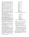
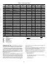
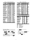
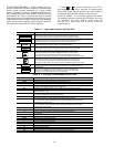
Table 7 lists the available controller set points and their
default values.
7. Pressing the button will take the user out of the
set point configuration mode.
ENTER
ENTER
CLEAR
SCHD
ENTER
ENTER
EXPN/EDIT
SCHD
ENTER
ENTER
EXPN/EDIT
CLEAR