


9
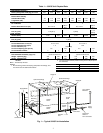
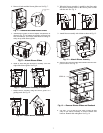
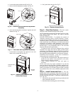
4. Loosen belt tension and take belt off. See Fig. 20.
5. Remove bolt-belt adjustment assembly. See Fig. 20.
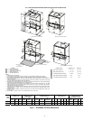
6. Move bolt-belt adjustment assembly to opposite side and
reattach. See Fig. 21.
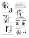
7. Put belt back on and tighten. Put control box cover and
motor cover on return side. See Fig. 22.
8. Put 3 panels back onto unit. See Fig. 23.
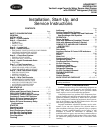
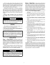
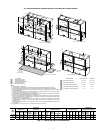
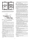
Step 5 — Check Duct System — The duct system
should be sized to handle the design airflow quietly.
NOTE: Depending on the unit, the fan wheel may have a ship-
ping support installed at the factory. This must be removed
before operating unit.
SOUND ATTENUATION — To eliminate the transfer of
vibration to the duct system, a flexible connector is recom-
mended for both discharge and return air duct connections on
metal duct systems. The supply and return plenums should in-
clude internal duct liner of fiberglass or be made of duct board
construction to maximize sound attenuation of the blower.
Installing the WSHP unit to uninsulated ductwork in an uncon-
ditioned space is not recommended since it will sweat and
adversely affect the unit’s performance.
To reduce air noise, at least one 90-degree elbow could be
included in the supply and return air ducts, provided system
performance is not adversely impacted. The blower speed can
be also changed in the field to reduce air noise or excessive air-
flow, provided system performance is not adversely impacted.
EXISTING DUCT SYSTEM — If the unit is connected to
existing ductwork, consider the following:
• Verify that the existing ducts have the proper capacity to
handle the unit airflow. If the ductwork is too small,
larger ductwork should be installed.
• Check existing ductwork for leaks and repair as
necessary.
NOTE: Local codes may require ventilation air to enter the
space for proper indoor air quality. Hard-duct ventilation may
be required for the ventilating air supply. If hard ducted venti-
lation is not required, be sure that a proper air path is provided
for ventilation air to unit to meet ventilation requirement of the
space.
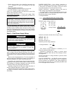
Step 6 — Install Condensate Drain — The con-
densate drain can be connected to either side of the unit. The
50VQP units come with a flex hose and 1 in. (25 m) FPT con-
densate connection tied inside. To install the condensate drain
(see Fig. 24.):
1. Untie the flex hose and make interal trap on either the left
side or right side of the unit.
2. Internally attach mounting plate with FPT fitting.
Fig. 20 — Remove Belt and Bolt-Belt Adjustment
Assembly
STEP 5
STEP 4
BOLT-BELT ADJUSTMENT ASM
a50-8482
Fig. 21 — Move Bolt-Belt Adjustment Assembly
STEP 6
a50-8483
Fig. 22 — Replace Belt and Motor and
Control Box Covers
CONTROL BOX
COVER
MOTOR
COVER
a50-8484
Fig. 23 — Replace Access Panels
FRONT RETURN TOP DISCHARGE
CONTROL
BOX
a50-8485