


37
Units with Aquazone™ Complete C Control
STANDBY — Y and W terminals are not active in Standby
mode, however the O and G terminals may be active, de-
pending on the application. The compressor will be off.
COOLING — Y and O terminals are active in Cooling
mode. After power up, the first call to the compressor will
initiate a 5 to 80 second random start delay and a 5-minute
anti-short cycle protection time delay. After both delays are
complete, the compressor is energized.
NOTE: On all subsequent compressor calls the random start
delay is omitted.
HEATING STAGE 1 — Terminal Y is active in heating
stage 1. After power up, the first call to the compressor will
initiate a 5 to 80 second random start delay and a 5-minute
anti-short cycle protection time delay. After both delays are
complete, the compressor is energized.
NOTE: On all subsequent compressor calls the random start
delay is omitted.
HEATING STAGE 2 — To enter Stage 2 mode, terminal W
is active (Y is already active). Also, the G terminal must be
active or the W terminal is disregarded. The compressor re-
lay will remain on and EH1 is immediately turned on. EH2
will turn on after 10 minutes of continual stage 2 demand.
NOTE: EH2 will not turn on (or if on, will turn off) if FP1
temperature is greater than 7.2 C and FP2 is greater than
48.9 C.
EMERGENCY HEAT — In emergency heat mode, termi-
nal W is active while terminal Y is not. Terminal G must be
active or the W terminal is disregarded. EH1 is immediately
turned on. EH2 will turn on after 5 minutes of continual
emergency heat demand.
Units with Aquazone Deluxe D Control
STANDBY/FAN ONLY — The compressor will be off.
The Fan Enable, Fan Speed, and reversing valve (RV) relays
will be on if inputs are present. If there is a Fan 1 demand,
the Fan Enable will immediately turn on. If there is a Fan 2
demand, the Fan Enable and Fan Speed will immediately
turn on.
NOTE: DIP switch 5 on S1 does not have an effect upon
Fan 1 and Fan 2 outputs.
HEATING STAGE 1 — In Heating Stage 1 mode, the Fan
Enable and Compressor relays are turned on immediately.
Once the demand is removed, the relays are turned off and
the control reverts to Standby mode. If there is a master/
slave or dual compressor application, all compressor relays
and related functions will operate per their associated DIP
switch 2 setting on S1.
HEATING STAGE 2 — In Heating Stage 2 mode, the Fan
Enable and Compressor relays are remain on. The Fan
Speed relay is turned on immediately and turned off imme-
diately once the demand is removed. The control reverts to
Heating Stage 1 mode. If there is a master/slave or dual
compressor application, all compressor relays and related
functions will operate per their associated DIP switch 2 set-
ting on S1.
HEATING STAGE 3 — In Heating Stage 3 mode, the Fan
Enable, Fan Speed and Compressor relays remain on. The EH1
output is turned on immediately. With continuing Heat Stage 3
demand, EH2 will turn on after 10 minutes. EH1 and EH2 are
turned off immediately when the Heating Stage 3 demand is re-
moved. The control reverts to Heating Stage 2 mode.
Output EH2 will be off if FP1 is greater than 7.2 C and
FP2 (when shorted) is greater than 48.9 C during Heating
Stage 3 mode. This condition will have a 30-second
recognition time. Also, during Heating Stage 3 mode, EH1,
EH2, Fan Enable, and Fan Speed will be ON if G input is
not active.
EMERGENCY HEAT — In Emergency Heat mode, the
Fan Enable and Fan Speed relays are turned on. The EH1
output is turned on immediately. With continuing Emergen-
cy Heat demand, EH2 will turn on after 5 minutes. Fan En-
able and Fan Speed relays are turned off after a 60-second
delay. The control reverts to Standby mode.
Output EH1, EH2, Fan Enable, and Fan Speed will be
ON if the G input is not active during Emergency Heat
mode.
COOLING STAGE 1 — In Cooling Stage 1 mode, the Fan
Enable, compressor and RV relays are turned on immediate-
ly. If configured as stage 2 (DIP switch set to OFF) then the
compressor and fan will not turn on until there is a stage 2
demand. The Fan Enable and compressor relays are turned
off immediately when the Cooling Stage 1 demand is re-
moved. The control reverts to Standby mode. The RV relay
remains on until there is a heating demand. If there is a mas-
ter/slave or dual compressor application, all compressor re-
lays and related functions will track with their associated
DIP switch 2 on S1.
COOLING STAGE 2 — In Cooling Stage 2 mode, the Fan
Enable, compressor and RV relays remain on. The Fan
Speed relay is turned on immediately and turned off once
the Cooling Stage 2 demand is removed. The control reverts
to Cooling Stage 1 mode. If there is a master/slave or dual
compressor application, all compressor relays and related
functions will track with their associated DIP switch 2 on
S1.
NIGHT LOW LIMIT (NLL) STAGED HEATING — In
NLL staged Heating mode, the override (OVR) input be-
comes active and is recognized as a call for heating and the
control will immediately go into a Heating Stage 1 mode.
With an additional 30 minutes of NLL demand, the control
will go into Heating Stage 2 mode. With another additional
30 minutes of NLL demand, the control will go into Heating
Stage 3 mode.
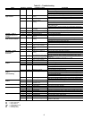
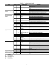
COMPLETE C AND DELUXE D BOARD
SYSTEM TEST
System testing provides the ability to check the control
operation. The control enters a 20-minute Test mode by mo-
mentarily shorting the test pins. All time delays are in-
creased 15 times.
Test Mode — To enter Test mode on Complete C or De-
luxe D controls, cycle the power 3 times within 60 seconds.
The LED (light-emitting diode) will flash a code representing
the last fault when entering the Test mode. The alarm relay will
also power on and off during Test mode. See Tables 20-22. To
exit Test mode, short the terminals for 3 seconds or cycle the
power 3 times within 60 seconds.
NOTE: The Deluxe D control has a flashing code and alarm
relay cycling code that will both have the same numerical
label. For example, flashing code 1 will have an alarm relay
cycling code 1. Code 1 indicates the control has not faulted
since the last power off to power on sequence.