


4
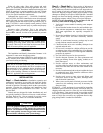
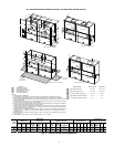
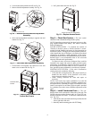
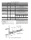
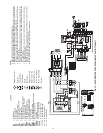
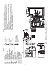
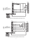
Fig. 2 — 50VQP084-150 Unit Dimensions
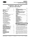
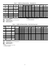
CONNECTIONS 50VQP084-120 50VQP150
Water Inlet (See Note 7) 1
1
/
2
in. FPT 2 in. FPT
Water Outlet (See Note 7) 1
1
/
2
in. FPT 2 in. FPT
Condensate Drain (See Note 8) 1 in. FPT 1 in. FPT
High Voltage Access (See Note 9) 1
3
/
8
in. 1
3
/
8
in.
Low Voltage Access (See Note 9)
7
/
8
in.
7
/
8
in.
1
2
3
4
5
a50-8436
UNIT
50VQP
OVERALL
CABINET (cm)
DISCHARGE
CONNECTIONS (cm)
Duct Flange
WATER
CONNECTIONS (cm)
ELECTRICAL
KNOCKOUTS (cm)
RETURN AIR
CONNECTIONS (cm)
(Using Return Air Opening)
A
Depth
B
Width
C
Height
D
Supply
Width
E
Supply
Depth
F
K
1-Water
Inlet
L
1-Water
Outlet
M
3-
Condesate
NO1O2P QR
S
Return
Depth
T
Return
Height
UV
084-120 86.4 134.9 200.7 44.5 44.6 45.1 78.7 7.6 68.6 65.1 78.7 96.4 87.7 2.5 7.6 121.9 82.2 113.3 6.9
150 86.4 134.9 200.7 54.4 44.6 45.1 78.7 7.6 68.6 65.1 78.7 96.4 87.7 2.5 7.6 121.9 82.2 113.3 6.9
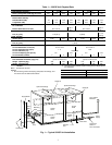
LEGEND
NOTES:
1. All dimensions in centimeters.
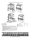
2. Units require 0.9 m clearance for water connections, CAP, CSP, MSP, and BSP service access.
3. Overall cabinet height dimension does not include duct flange when in top discharge configuration.
4. Overall cabinet width dimension does not include filter rack and duct flange when on front or back dis-
charge configuration.
5. Side service access must be 0.9 m on either side that connections are made. If no connections are made
on a side, then service access can be 15 mm minimum.
6. While access to all removable panels is not required, installer should take care to comply with all building
codes and allow adequate clearance for future field service.
7. Water inlet and water outlet connections are available on either side (left or right) of the unit. Two MPT
plugs are shipped loose in a plastic bag tied to the water leg in front of the unit. Installer must plug water
inlet/outlet side not being connected to.
8. Condensate drain is available on either side (left or right) of unit. Drain hose and drain connection will be
tied inside the unit. Installer must untie the drain hose and connect to the condensate drain hole of
installer’s choice.
9. Electrical access is available on either side (left or right) of unit and is also available (left or right) in the
front of the unit.
10. Overall depth — add 7.9 cm for 2.5 or 5 cm filter. Add 13 cm for 10 cm filter.
BSP —Blower Service Panel
CAP — Control Access Panel
CSP — Compressor Service Panel
MSP — Motor Service Panel
NRP — Non-Removable Panel
ALL CONFIGURATIONS REQUIRE SERVICE ACCESS AREA SHOWN BELOW
FRONT RETURN TOP DISCHARGE
NRP
AIR OUT
BSP
AIR OUT
AIR OUT
AIR OUT
NRP
NRP
NRP
NRP
NRP
NRP
NRP
NRP
NRP
Control Box
Control Box
Control Box
Control Box
NRP
CAP+MSP
RETURN AIR
RETURN AIR
RETURN AIR
RETURN AIR
BSP
BSP
BSP
CSP
CSP
BSP
N
2
2
2
2
3
3
3
3
3
3
4
4
5
5
4
4
3
4
4
5
3
4
4
5
CAP+MSP
CSP+CAP+MSP
1
1
1
1
01
02
C
P
CSP+CAP+MSP
A
NOTE 5
Q
R
S
19.3
B
D
F
T
U
L
K
M
REAR RETURN TOP DISCHARGE
4
4
5
4
4
5
19.3
F
L
K
M
REAR RETURN FRONT DISCHARGE
FRONT RETURN REAR DISCHARGE
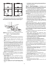
SIDE
SERVICE ACCESS
(SEE NOTE)
SERVICE ACCESS
91 CM
FRONT AND BACK
4.3
E
F
D
F