


7
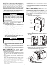
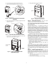
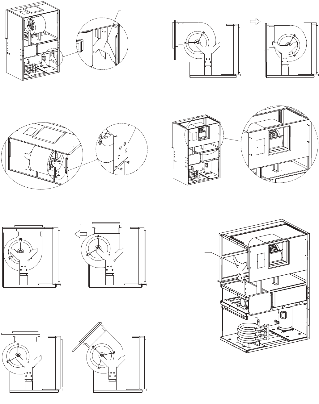
4. Remove 4 bolts and take blower glides out. See Fig. 7.
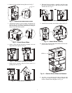
5. Attach blower glides to blower bottom load brackets as
shown in Fig. 8. Use bottom set of holes on blower bot-
tom load brackets. The blower shaft should be sitting di-
rectly on top of the blower glides.
6. Stand in front and pull the blower assembly on to the
ridge of the blower glides. See Fig. 9.
7. Rotate blower assembly using the blower glides as a
guiding track. See Fig. 10.
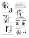
8. When the blower assembly is parallel to the floor, push
the blower assembly back so the blower panel is flush
with the unit. See. Fig. 11.
9. Attach blower assembly with 4 bolts as shown in Fig. 12.
10. Remove the 2 blower glides and reattach back into com-
pressor section. See Fig. 13.
11. Use four
1
/
4
in. (6 mm) 20 UNC bolts (2 bolts on each
side) to bolt blower assembly to blower bottom load
brackets. Reattach belt and tighten. See Fig. 14.
Fig. 7 — Remove Bolts and Blower Glides
BLOWER GLIDES
(2X)
a50-8469
Fig. 8 — Attach Blower Glides
a50-8470
Fig. 9 — Pull Blower Assembly to Glides
a50-8471
Fig. 10 — Rotate Blower Assembly
a50-8472
Fig. 11 — Push in Blower Assembly
a50-8473
Fig. 12 — Attach Blower Asembly
a50-8474
Fig. 13 — Remove Blower Glides and Reattach
STEP 10
a50-8475