


13
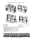
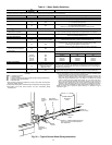
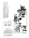
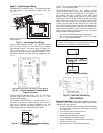
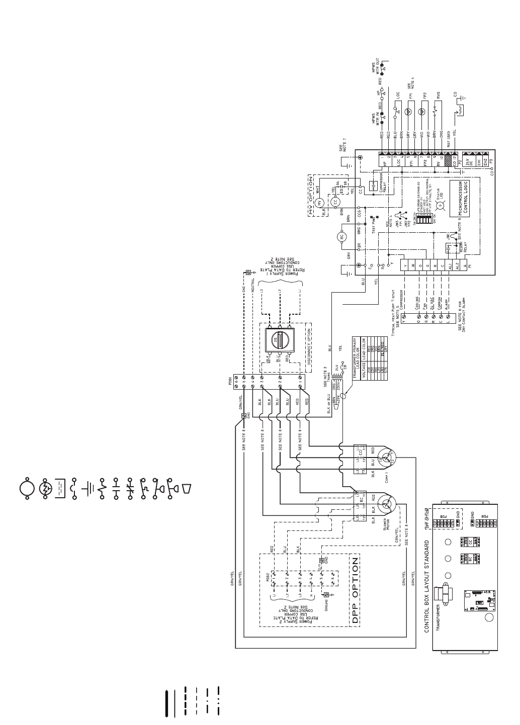
Fig. 27 — 50VQP084-168 Unit with Complete C Control (Typical)
a50-8438
NOTES:
1. Compressor and blower motor thermally protected internally.
2. All wiring to the unit must comply with NEC (National Electrical Code, U.S.A.) and local codes.
3. 380/420-v transformers will be connected for 380-v operation. For 420-v operation, disconnect
VIO lead at L1, and attach BRN lead to L1. Close open end of VIO lead.
4. FPI jumper provides low temperature protection for WATER. When using ANTIFREEZE solu-
tions, cut JW3 jumper.
5. Typical heat pump thermostat wiring shown. Refer to thermostat installation instructions for wir-
ing to the unit. Thermostat wiring must be “Class 1” and voltage rating equal to or greater than
unit supply voltage.
6. 24-v alarm signal shown. For dry alarm contact, cut JW1 jumper and dry contact will be avail-
able between AL1 and AL2.
7. Transformer secondary ground via Complete C board standoffs and screws to control box.
(Ground available from top two standoffs as shown.)
8. For dual point power option, blower wires (3 qty) will go to PDB2 only.
AL — Alarm Relay
BC — Blower Contactor
CB — Circuit Breaker
CC — Compressor Contactor
CO — Sensor, Condensate Overflow
DPP — Dual Point Power
DS — Disconnect Switch
FP1 — Sensor, Water Coil Freeze Protection
FP2 — Sensor, Air Coil Freeze Protection
HP — High-Pressure Switch
HPWS — High-Pressure Water Switch
JW3 — Clippable Field Selection Jumper
LOC — Loss of Charge Pressure Switch
MV — Motorized Valve
PDB1 — Power Distribution Block
PDB2 — Power Distribution Block Dual Point Option
RVS — Reversing Valve Solenoid
TRANS — Transformer
Factory Line Voltage Wiring
Factory Low Voltage Wiring
Field Line Voltage Wiring
Field Low Voltage Wiring
Printed Circuit Trace
Optional Wiring
LEGEND
Relay/Contactor Coil
Thermistor
Condensate Pan
Circuit Breaker
Ground
Solenoid Coil
Relay Contacts - N.O.
Relay Contacts - N.C.
Temperature Switch
Switch - Low Pressure
Switch - High Pressure
Wire Nut
Complete C