


8
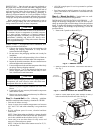
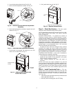
12. Reattach blockoff air handler as shown in Fig. 15.
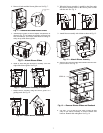
13. Put 3 panels back onto unit. See Fig. 16.
Sound minimization is achieved by enclosing the unit with-
in a small mechanical room or a closet. The following are addi-
tional measures for sound control.
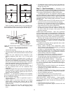
1. Mount the unit so that the return-air inlet is 90 degrees to
the return-air grille. Install a sound baffle to reduce line-
of-sight sound transmitted through return-air grilles.
2. Mount the unit on a rubber or neoprene pad to minimize
vibration transmission to the building structure. Extend
the pad beyond all four edges of the unit.
NOTE: Some codes require the use of a secondary drain pan
under vertical units. Check local codes for more information.
CONTROL BOX/MOTOR ACCESS CONFIGURATION
CONVERSION — To change the configuration of the control
box/motor access from the front of the unit to the back of the
unit, follow the procedure below. To change the configuration
of the control box/motor access from the back of the unit to the
front of the unit, reverse the procedure below.
1. Remove the 3 panels as shown in Fig. 17.
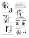
2. Remove motor cover and control box cover as shown in
Fig. 18.
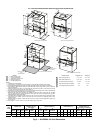
3. Remove 4 screws from control box. Using the guide rails
as a guide, flip the control box down, slide the box across,
and then flip the box up as shown in Fig. 19. Reattach the
control box with screws.
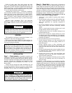
Fig. 15 — Reattach Blockoff Air Handler
BLOCKOFF
AIR HANDLER
a50-8477
Fig. 16 — Replace Panels
BLOWER FILLER
PANEL
C-BOX/MOTOR ACCESS
PANEL
COMPRESSOR
PANEL ACCESS
a50-8478
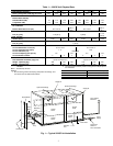
Fig. 17 — Remove Access Panels
FRONT C-BOX/
MOTOR ACCESS
PANEL
COMPRESSOR
ACCESS PANEL
BACK COMPRESSOR/
C-BOX/ MOTOR ACCESS
PANEL
RETURN
AIR
CONTROL
BOX
a50-8479
Fig. 18 — Remove Motor and Control Box Covers
MOTOR
COVER
CONTROL BOX COVER
a50-8480
Fig. 19 — Flip Control Box
RIGHT SIDE VIEW
SCREWS
A
C
B
a50-8481
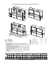
Fig. 14 — Bolt Blower Assembly to Load Brackets
a50-8476