


10
Each unit must be installed with its own individual trap,
vent and means to flush or blow out the condensate drain line.
Do not install units with a common trap or vent. See Fig. 25.
Consider the following:
• Units are typically installed directly above each other on
successive floors with condensate drains located near the
units.
• Connect the unit condensate drain connection to the
building condensate drain with a 1-in. (25 mm) drain
line.
• The horizontal run of a condensate hose is usually too
short to cause drainage problems, however the horizontal
run pitch of the condensate line should be at least 1 cm
for every 50 cm of run in the direction of flow. Avoid low
points and unpitched piping since dirt collects in low or
level areas and may cause stoppage and overflow.
• Install a condensate trap at each unit with the top of
the trap positioned below the unit condensate drain
connection.
• Design the length of the trap (water-seal) based upon the
amount of positive or negative pressure on the drain pan.
As a rule, 25 mm of trap is required for each 10 Pa of
negative pressure on the unit.
VENTING — A vent should be installed in the condensate
line of any application which may allow dirt or air to collect in
the line. Consider the following:
• Always install a vent where an application requires a
long horizontal run.
• Always install a vent where large units are working
against higher external static pressure and to allow
proper drainage for multiple units connected to the same
condensate main.
• Be sure to support the line where anticipated sagging
from the condensate or when “double trapping” may
occur.
• If condensate pump is present on unit, be sure drain con-
nections have a check valve to prevent back flow of con-
densate into other units.
Step 7 — Pipe Connections — Depending on the
application, there are 3 types of WSHP piping systems to choose
from: water loop, ground-water and ground loop. Refer to the
Carrier System Design Manual for additional information.
All WSHP units utilize low temperature soldered female
pipe thread fittings for water connections to prevent annealing
and out-of-round leak problems which are typically associated
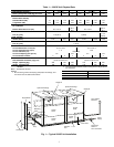
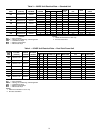
with high temperature brazed connections. Refer to Table 1 for
connection sizes. When making piping connections, consider
the following:
• A backup wrench must be used when making screw con-
nections to unit to prevent internal damage to piping.
• Insulation may be required on piping to avoid condensa-
tion in the case where fluid in loop piping operates at
temperatures below dew point of adjacent air.
• Piping systems that contain steel pipes or fittings may
be subject to galvanic corrosion. Dielectric fittings may
be used to isolate the steel parts of the system to avoid
galvanic corrosion.
WATER LOOP APPLICATIONS — Water loop applications
usually include a number of units plumbed to a common pip-
ing system. Maintenance to any of these units can introduce air
into the piping system. Therefore, air elimination equipment
comprises a major portion of the mechanical room plumbing.
The flow rate is usually set between 2.41 and 3.23 L/m per
kW of cooling capacity. For proper maintenance and servicing,
pressure-temperature (P/T) ports are necessary for temperature
and flow verification.
In addition to complying with any applicable codes, consid-
er the following for system piping:
• Piping systems utilizing water temperatures below
10.0 C require 13 mm closed cell insulation on all piping
surfaces to eliminate condensation.
• All plastic to metal threaded fittings should be avoided
due to the potential to leak. Use a flange fitted substitute.
• Teflon tape thread sealant is recommended to minimize
internal fouling of the heat exchanger.
• Use backup wrench. Do not overtighten connections.
• Route piping to avoid service access areas to unit.
• The piping system should be flushed prior to operation to
remove dirt and foreign materials from the system.
GROUND-LOOP APPLICATIONS — Temperatures be-
tween –3.9 and 43.3 C and a cooling capacity of 2.41 to
3.23 L/s per kW are recommended. In addition to comply-
ing with any applicable codes, consider the following for
system piping:
• Piping materials should be limited to only polyethylene
fusion in the buried sections of the loop.
• Galvanized or steel fittings should not be used at any
time due to corrosion.
• All plastic to metal threaded fittings should be avoided
due to the potential to leak. Use a flange fitted substitute.
• Do not overtighten connections.
• Route piping to avoid service access areas to unit.
• Pressure-temperature (P/T) plugs should be used to mea-
sure flow of pressure drop.
GROUND-WATER APPLICATIONS — Typical ground-
water piping is shown in Fig. 26. In addition to complying
with any applicable codes, consider the following for sys-
tem piping:
• Install shut-off valves for servicing.
• Install pressure-temperature plugs to measure flow and
temperature.
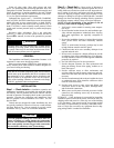
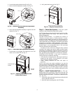
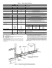
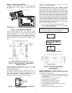
NOTE: Trap should be deep enough to offset maximum unit static
difference.
Fig. 25 — Trap Condensate Drain
*3/4" IPT
Trap Depth
1.5" [38mm]
Min 1.5"
[38mm]
1/4" per foot
(21mm per m)
drain slope
3/4" PVC or
Copper by others
Vent
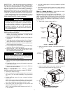
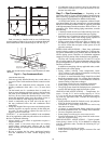
Fig. 24 — Install Condensate Drain
a50-8486