


18
9. Condensate line is open and correctly pitched.
10. Transformer switched to lower voltage tap if necessary.
11. Blower rotates freely — shipping support is removed.
12. Blower speed is on correct setting.
13. Air filter is clean and in position.
14. Service/access panels are in place.
15. Return-air temperature is 4.4 to 26.7 C for heating and
10.0 to 43.3 C for cooling.
16. Air coil is clean.
17. Control field-selected settings are correct.
AIR COIL — To obtain maximum performance, the air coil
should be cleaned before starting the unit. A 10% solution of
dishwasher detergent and water is recommended for both sides
of the coil. Rinse thoroughly with water.
Airflow and External Static Pressure — The
50VQP units are available with standard, low, and high-static
factory-installed options. These options will substitute a differ-
ent blower drive sheave for each static range. In addition, cer-
tain static ranges may require the optional large fan motor.
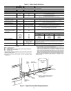
SHEAVE ADJUSTMENT — The 50VQP units are supplied
with a variable sheave drive on the fan motor to adjust for dif-
fering airflows at various ESP (external static pressure) condi-
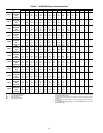
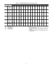
tions. See Tables 5-12 for unit airflows. When fully closed, the
sheave will produce the highest static capability (higher rpm).
To adjust sheave position, follow the procedure outlined below:
1. Loosen belt tension and remove belt.
2. Loosen set screw on fan motor.
3. Open sheave to desired position.
4. Retighten set screw and replace belt.
NOTE: Set belt tension as outlined below.
BELT TENSION ADJUSTMENT — An overly loose belt
will, upon starting motor, produce a slippage “squeal” and
cause premature belt failure and or intermittent airflow. An
overly tight belt can cause premature motor or blower bear-
ing failure. To adjust the belt tension, follow the procedure
outlined below:
1. Remove belt from motor sheave.
2. Lift motor assembly.
3. Loosen the
5
/
16
-in. hex nuts on the grommet motor adjust-
ment bolts (2 per bolt). To increase the belt tension loosen
the top hex nut. To decrease the belt tension loosen the
bottom hex nut.
4. Turn the bolts by hand to the desired position then tighten
the
5
/
16
-in. hex nuts (2 per bolt).
5. Lower the motor assembly.
6. Install the belt.
7. The belt tension can be adjusted by using one of the fol-
lowing methods:
a. Tighten until belt deflects approximately 13 mm
with very firm finger pressure.
b. Grasp belt midway between two pulleys and twist
for a 90-degreerotation.
NOTE: Adjusting less than 90 degreeswill over-
tighten the belt and adjusting more than 90degrees
will loosen belt.
c. Set proper belt tension to 32 to 36 kg.
NOTE: The motor position should not need adjustment. Motor
sheave position is at mid position of each sheave. For example,
the motor sheave is 2.5 turns open on a 5-turn sheave. The belt
tension adjustment can also be accomplished by turning the
5
/
16
-in. hex nuts to the desired position.
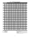
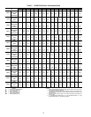
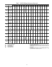
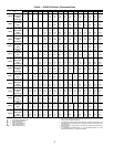
NOTE: Available airflows for all units are shown in
Tables 5-12.