


39
Retry Mode — In Retry mode, the status LED will start to
flash slowly to signal that the control is trying to recover from
an input fault. The control will stage off the outputs and try to
again satisfy the thermostat used to terminal Y. Once the ther-
mostat input calls are satisfied, the control will continue normal
operation.
NOTE: If 3 consecutive faults occur without satisfying the
thermostat input call to terminal Y, the control will go into
lockout mode. The last fault causing the lockout is stored in
memory and can be viewed by entering Test mode.
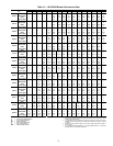
Aquazone™ Deluxe D Control LED Indica-
tors — There are 3 LED indicators on the Deluxe D control:
STATUS LED — Status LED indicates the current status or
mode of the Deluxe D control. The Status LED light is green.
TEST LED — Test LED will be activated any time the De-
luxe D control is in Test mode. The Test LED light is yellow.
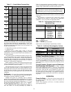
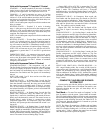
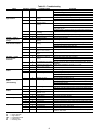
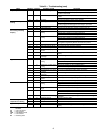
FAULT LED — Fault LED light is red. The fault LED will
always flash a code representing the last fault in memory. If
there is no fault in memory, the fault LED will flash code 1 and
appear as 1 fast flash alternating with a 10-second pause. See
Table 22.
SERVICE
Perform the procedures outlined below periodically, as
indicated.
Filters — Filters must be clean for maximum performance.
Inspect filters every month under normal operating conditions.
replace when necessary.
Water Coil — Keep all air out of the water coil. Check
open loop systems to be sure the well head is not allowing air
to infiltrate the water line. Always keep lines airtight.
Inspect heat exchangers regularly, and clean more frequent-
ly if the unit is located in a “dirty” environment. The heat
exchanger should be kept full of water at all times. Open loop
systems should have an inverted P trap placed in the discharge
line to keep water in the heat exchanger during off cycles.
Closed loop systems must have a minimum of 100 kPa during
the summer and 275 kPa during the winter.
Check P trap frequently for proper operation.
Condensate Drain Pans — Check condensate drain
pans for algae growth twice a year. If algae growth is apparent,
consult a water treatment specialist for proper chemical treat-
ment. The application of an algaecide every three months will
typically eliminate algae problems in most locations.
Refrigerant System — Verify air and water flow rates
are at proper levels before servicing. To maintain sealed circuit-
ry integrity, do not install service gages unless unit operation
appears abnormal.
Condensate Drain Cleaning — Clean the drain line
and unit drain pan at the start of each cooling season. Check
flow by pouring water into drain. Be sure trap is filled to main-
tain an air seal.
Air Coil Cleaning — Remove dirt and debris from evap-
orator coil as required by condition of the coil. Clean coil with
a stiff brush, vacuum cleaner, or compressed air. Use a fin
comb of the correct tooth spacing when straightening mashed
or bent coil fins.
Condenser Cleaning — Water-cooled condensers may
require cleaning of scale (water deposits) due to improperly
maintained closed-loop water systems. Sludge build-up may
need to be cleaned in an open water tower system due to
induced contaminants.
Local water conditions may cause excessive fouling or
pitting of tubes. Condenser tubes should therefore be cleaned at
least once a year, or more often if the water is contaminated.
Proper water treatment can minimize tube fouling and
pitting. If such conditions are anticipated, water treatment
analysis is recommended. Refer to the Carrier System Design
Manual, Part 5, for general water conditioning information.
Clean condensers with an inhibited hydrochloric acid solu-
tion. The acid can stain hands and clothing, damage concrete,
and, without inhibitor, damage steel. Cover surroundings to
guard against splashing. Vapors from vent pipe are not harmful,
but take care to prevent liquid from being carried over by the
gases.
Warm solution acts faster, but cold solution is just as effec-
tive if applied for a longer period.
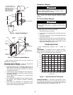
GRAVITY FLOW METHOD — Do not add solution faster
than vent can exhaust the generated gases.
When condenser is full, allow solution to remain overnight,
then drain condenser and flush with clean water. Follow acid
manufacturer’s instructions. See Fig. 36.
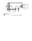
FORCED CIRCULATION METHOD — Fully open vent
pipe when filling condenser. The vent may be closed when
condenser is full and pump is operating. See Fig. 37.
Regulate flow to condenser with a supply line valve. If
pump is a nonoverloading type, the valve may be fully closed
while pump is running.
For average scale deposit, allow solution to remain in con-
denser overnight. For heavy scale deposit, allow 24 hours.
IMPORTANT: When a compressor is removed from this
unit, system refrigerant circuit oil will remain in the com-
pressor. To avoid leakage of compressor oil, the refrigerant
lines of the compressor must be sealed after it is removed.
IMPORTANT: All refrigerant discharged from this unit
must be recovered without exception. Technicians must fol-
low industry accepted guidelines and all local, state and fed-
eral statutes for the recovery and disposal of refrigerants.
IMPORTANT: To avoid the release of refrigerant into the
atmosphere, the refrigerant circuit of this unit must only be
serviced by technicians which meet local, state and federal
proficiency requirements.
IMPORTANT: To prevent injury or death due to electrical
shock or contact with moving parts, open unit disconnect
switch before servicing unit.
IMPORTANT: Units should never be operated with-
out a filter.
IMPORTANT: To avoid fouled machinery and extensive
unit clean-up, DO NOT operate units without filters in
place. DO NOT use equipment as a temporary heat source
during construction.
CAUTION
Follow all safety codes. Wear safety glasses and rubber
gloves when using inhibited hydrochloric acid solution.
Observe and follow acid manufacturer’s instructions. Fail-
ure to follow these safety precautions could result in per-
sonal injury or equipment or property damage.