


11
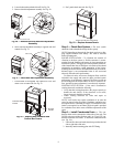
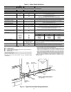
• Boiler drains and other valves should be connected using
a “T” connector to allow acid flushing for the heat
exchanger.
• Do not overtighten connections.
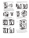
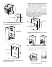
• Route piping to avoid service access areas to unit.
• Use PVC SCH80 or copper piping material.
NOTE: PVC SCH40 should not be used due to system high
pressure and temperature extremes.
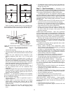
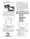
Water Supply and Quantity
— Check water supply. Water
supply should be plentiful and of good quality. See Table 2 for
water quality guidelines.
In all applications, the quality of the water circulated
through the heat exchanger must fall within the ranges listed in
the Water Quality Guidelines table. Consult a local water treat-
ment firm, independent testing facility, or local water authority
for specific recommendations to maintain water quality within
the published limits.
Step 8 — Field Power Supply Wiring
All field-installed wiring, including the electrical ground,
MUST comply with the National Electrical Code (NEC) as
well as applicable local codes. In addition, all field wiring must
conform to the Class II temperature limitations described in the
NEC.
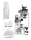
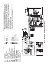
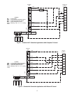
Refer to unit wiring diagrams Fig. 27-30 for a schematic of
the field connections which must be made by the installing (or
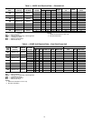
electrical) contractor. See Tables 3 and 4 for fuses sizes.
Consult the unit wiring diagram located on the inside of the
compressor access panel to ensure proper electrical hookup.
The installing (or electrical) contractor must make the field
connections when using field-supplied disconnect.
Operating voltage must be the same voltage and phase as
shown in electrical data shown in Tables 3 and 4.
Make all final electrical connections with a length of flexi-
ble conduit to minimize vibration and sound transmission to
the building.
POWER CONNECTION — Line voltage connection is
made by connecting the incoming line voltage wires to the
L side of the CC terminal. See Tables 3 and 4 for correct
wire and maximum overcurrent protection sizing.
SUPPLY VOLTAGE — Operating voltage to unit must be
within voltage range indicated on unit nameplate.
On 3-phase units, voltages under load between phases must
be balanced within 2%. Use the following formula to deter-
mine the percentage voltage imbalance:
% Voltage Imbalance
Example: Supply voltage is 420-3-50.
AB = 425 volts
BC = 422 volts
AC = 417 volts
Determine maximum deviation from average voltage:
(AB) 425 – 421 = 4 v
(BC) 422 – 421 = 1 v
(AC) 421 – 418 = 3 v
Maximum deviation is 4 v.
Determine percent voltage imbalance.
= 0.95%
This amount of phase imbalance is satisfactory as it is
below the maximum allowable 2%.
Operation on improper line voltage or excessive phase
imbalance constitutes abuse and may cause damage to electri-
cal components.
NOTE: If more than 2% voltage imbalance is present, contact
local electric utility.
420-VOLT OPERATION — All 380/420 volt units are factory
wired for 380 volts. The transformers may be switched to
420-volt operation (as illustrated on the wiring diagram) by
disconnecting the VIO lead at L1 and attaching the BRN lead
to L1. Close open end of VIO lead.
IMPORTANT: Failure to comply with the above required
water quality and quantity limitations and the closed-
system application design requirements may cause damage
to the tube-in-tube heat exchanger that is not the responsi-
bility of the manufacturer.
WARNING
To avoid possible injury or death due to electrical shock,
open the power supply disconnect switch and secure it in
an open position during installation.
CAUTION
Use only copper conductors for field-installed electrical
wiring. Unit terminals are not designed to accept other
types of conductors.
= 100 x
max voltage deviation from average voltage
average voltage
Average Voltage =
425 + 422 + 417
3
=
1264
3
= 421
% Voltage Imbalance = 100 x
4
421