


6
PROTECTION — Once the units are properly positioned on
the jobsite, they must be covered with either a shipping carton,
vinyl film, or an equivalent protective covering. Open ends of
pipes stored on the jobsite must be capped. This precaution is
especially important in areas where painting, plastering, or
spraying of fireproof material, etc. is not yet complete. Foreign
material that is allowed to accumulate within the units can pre-
vent proper start-up and necessitate costly clean-up operations.
Before installing any of the system components, be sure to
examine each pipe, fitting, and valve, and remove any dirt or
foreign material found in or on these components.
INSPECT UNIT — To prepare the unit for installation, com-
plete the procedures listed below:
1. Compare the electrical data on the unit nameplate with
ordering and shipping information to verify that the
correct unit has been shipped.
2. Do not remove the packaging until the unit is ready for
installation.
3. Verify that the unit’s refrigerant tubing is free of kinks or
dents, and that it does not touch other unit components.
4. Inspect all electrical connections. Be sure connections are
clean and tight at their terminations.
5. Loosen compressor bolts until the compressor rides freely
on springs. Remove shipping restraints.
6. Remove the four
1
/
4
in. (6 mm) shipping bolts from com-
pressor support plate (two bolts on each side) to maxi-
mize vibration and sound alternation.
7. Remove any blower support cardboard from inlet of the
blower.
8. Locate and verify any accessory kit located in compressor
and/or blower section.
9. Remove any access panel screws that may be difficult to
remove once unit is installed.
Step 3 — Locate Unit — The following guidelines
should be considered when choosing a location for a WSHP:
• Units are for indoor use only.
• Locate in areas where ambient temperatures are between
4.4 C and 37.8 C and relative humidity is no greater than
75%.
• Provide sufficient space for water, electrical and duct
connections.
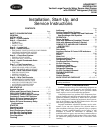
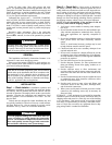
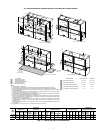
NOTE: Water inlets/outlets and high/low voltage electrical
access are available on either side of the unit. Electrical ac-
cess is also available on the unit front. See Fig. 2 and 3.
• Locate unit in an area that allows for easy access and
removal of filter and access panels.
NOTE: Unit has full filter frame bottom access for 25, 51,
or 102 mm filters.
• ALLOW enough space for service personnel to perform
maintenance.
• Provisions must be made for return air to freely enter the
space if unit needs to be installed in a confined area such
as a closet.
Step 4 — Mount the Unit — Vertical units are avail-
able in rear or front return air configurations.
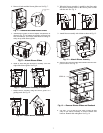
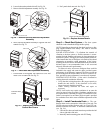
DISCHARGE CONFIGURATION CONVERSION — To
change the discharge configuration of the unit from top dis-
charge to straight (right or left) discharge, follow the procedure
below. To change the discharge configuration of the unit from
straight (right or left) discharge to top discharge, reverse the
procedure below.
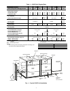
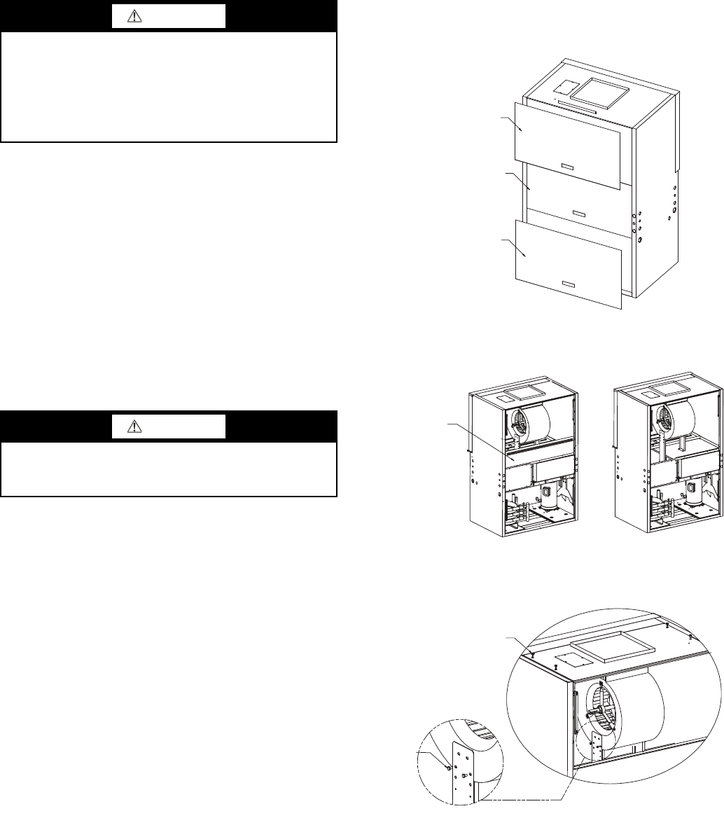
1. Remove the 3 panels as shown in Fig. 4.
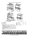
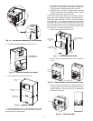
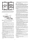
2. Remove blockoff air handler. Loosen belt and remove.
See. Fig. 5.
3. Remove 4 bolts from blower panel. Remove 4 bolts (2
bolts on each side) from blower sides. See Fig. 6.
CAUTION
DO NOT store or install units in corrosive environments or
in locations subject to temperature or humidity extremes
(e.g., attics, garages, rooftops, etc.). Corrosive conditions
and high temperature or humidity can significantly reduce
performance, reliability, and service life. Always move
units in an upright position. Tilting units on their sides may
cause equipment damage.
CAUTION
Failure to remove shipping brackets from spring-mounted
compressors will cause excessive noise and could cause
component failure due to added vibration.
Fig. 4 — Remove Panels
BLOWER ACCESS
PANEL
C-BOX/
MOTOR ACCESS
PANEL
COMPRESSOR
ACCESS PANEL
a50-8466
Fig. 5 — Remove Blockoff Air Handler and Belt
BLOCKOFF
AIR HANDLER
a50-8467
Fig. 6 — Remove Bolts from
Blower Panel and Sides
STEP 3
STEP 3
a50-8468