


35
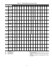
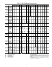
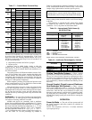
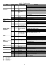
Table 15 — 50VQP Unit Operating Limits
LEGEND
*Requires optional insulation package when operating below the
dew point.
†With antifreeze, optional extended range insulation and low tem-
perature cutout jumper clipped for antifreeze.
If the suction pressure does not drop and the discharge
pressure does not rise to normal levels:
1. Turn off power to the unit. Install disconnect tag.
2. Reverse any two of the unit power leads.
3. Reapply power to the unit and verify pressures are correct.
The suction and discharge pressure levels should now move
to their normal start-up levels.
When the compressor is rotating in the wrong direction, the
unit makes an elevated level of noise and does not provide
cooling.
After a few minutes of reverse operation, the scroll com-
pressor internal overload protection will open, thus activating
the unit lockout. This requires a manual reset. To reset, turn the
thermostat on and then off.
NOTE: There is a 5-minute time delay before the compressor
will start.
Unit Start-Up Cooling Mode
1. Adjust the unit thermostat to the warmest position.
Slowly reduce the thermostat position until the compres-
sor activates.
2. Check for cool air delivery at unit grille a few minutes
after the unit has begun to operate.
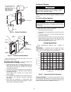
3. Verify that the compressor is on and that the water flow
rate is correct by measuring pressure drop through the
heat exchanger using P/T plugs. See Table 16. Check the
elevation and cleanliness of the condensate lines; any
dripping could be a sign of a blocked line. Be sure the
condensate trap includes a water seal.
4. Check the temperature of both supply and discharge wa-
ter. If temperature is within acceptable range, proceed. If
temperature is outside the range, check the cooling refrig-
erant pressures.
5. Check air temperature drop across the coil when com-
pressor is operating. Air temperature drop should be
between 8 and 14 C.
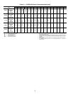
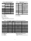
Table 16 — Water Temperature Change
Through Heat Exchanger
Unit Start-Up Heating Mode
NOTE: Operate the unit in heating cycle after checking the
cooling cycle. Allow 5 minutes between tests for the pressure
or reversing valve to equalize.
1. Turn thermostat to lowest setting and set thermostat
switch to HEAT position.
2. Slowly turn the thermostat to a higher temperature until
the compressor activates.
3. Check for warm air delivery at the unit grille within a few
minutes after the unit has begun to operate.
4. Check the temperature of both supply and discharge wa-
ter. If temperature is within acceptable range, proceed. If
temperature is outside the range, check the heating refrig-
erant pressures.
5. Once the unit has begun to run, check for warm air deliv-
ery at the unit grille.
6. Check air temperature rise across the coil when compres-
sor is operating. Air temperature rise should be between
11° C and 17° C after 15 minutes at load.
7. Check for vibration, noise and water leaks.
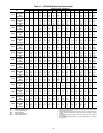
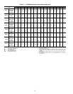
Flow Regulation — Flow regulation can be accom-
plished by two methods. Most water control valves have a flow
adjustment built into the valve. By measuring the pressure drop
through the unit heat exchanger, the flow rate can be deter-
mined using Table 17. Adjust the water control valve until the
flow of 0.09 to 0.13 L/s is achieved. Since the pressure con-
stantly varies, two pressure gages may be needed in some
applications.
An alternative method is to install a flow control device.
These devices are typically an orifice of plastic material de-
signed to allow a specified flow rate that are mounted on the
outlet of the water control valve. Occasionally these valves
produce a velocity noise that can be reduced by applying
some back pressure. To accomplish this, slightly close the
leaving isolation valve of the well water setup.
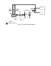
Flushing — Once the piping is complete, final purging
and loop charging is needed. A flush cart pump of at least
1.5 hp is needed to achieve adequate flow velocity in the
loop to purge air and dirt particles from the loop. Flush the
loop in both directions with a high volume of water at a high
velocity. Follow the steps below to properly flush the loop:
1. Verify power is off.
2. Fill loop with water from hose through flush cart be-
fore using flush cart pump to ensure an even fill. Do
not allow the water level in the flush cart tank to drop
below the pump inlet line to prevent air from filling
the line.
3. Maintain a fluid level in the tank above the return tee
to avoid air entering back into the fluid.
4. Shutting off the return valve that connects into the
flush cart reservoir will allow 345 kPa surges to help
purge air pockets. This maintains the pump at 345 kPa.
5. To purge, keep the pump at 345 kPa until maximum
pumping pressure is reached.
6. Open the return valve to send a pressure surge through
the loop to purge any air pockets in the piping system.
7. A noticeable drop in fluid level will be seen in the
flush cart tank. This is the only indication of air in the
loop.
AIR LIMITS COOLING (C) HEATING (C)
Minimum Ambient Air db 10 10
Rated Ambient Air db 27 20
Maximum Ambient Air db 38 29
Minimum Return Air db/wb 18/15 16
Maximum Return Air db/wb 43/28 29
WATER LIMITS
Standard Unit
Minimum Entering Water* 10 16
Maximum Entering Water 49 43
Extended Range Unit†
Minimum Entering Water* –1 –6.7
Maximum Entering Water 49 43
db — Dry Bulb
wb — Wet Bulb
WATER FLOW RATE (GPM)
COOLING
RISE (C)
HEATING
DROP (C)
Min Max Min Max
For Closed Loop: Ground Source or
Cooling/Boiler Systems at 3.9 L/m per kW
5.0 6.7 2.2 6.1
For Open Loop: Ground Water Systems at
2.0 L/m per kW
10.0 12.8 3.9 11.1
WARNING
To avoid possible injury or death due to electrical shock,
open the power supply disconnect switch and secure it in
an open position before flushing system.