


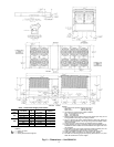

Chart 1, Field Power Supply Connections
UNIT
38AH
VOLTAGE Hz
DIAMETER
(in.)
QUANTITY
124A
124B
208/230 60 3
5
⁄
8
(92) 1
460, 575,
380
60 2
1
⁄
2
(63) 1
346, 380/415 50 3
5
⁄
8
(92) 1
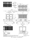
LEGEND
C—Copper Fin Coils
MTG — Mounting
SAE — Society of Automotive Engineers
NOTES:
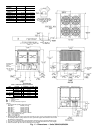
1. The approximate operating weight of the unit is:
38AH-124--- 7260 lb (3293 kg)
38AH-124--C 8126 lb (3686 kg)
2. Unit must have clearances for airflow as follows:
Top — Do not restrict in any way.
Ends—5ft[1524 mm]
Sides—6ft[1829 mm]
3. Mountingholes may be usedto mount unit to concretepad. They arenot rec-
ommended for mounting unit to spring isolators.
4. One 3
5
⁄
8
Љ (92-mm) dia hole is recommended for single-entry power into each
module (124A and 124B) of the 208/230-v units.
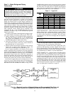
5. Circled numerals in Top View refer to condenser fans by position.
6. Ifspring isolatorsare used, aperimeter supportchannel between theunit and
the isolators is recommended. Do not support each module separately.
7. Eachmodule ofthe unitmust berigged intoposition separately.The unitmust
not be rigged after modules have been connected.
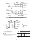
8. Suction and liquid connections can exit on either side of the unit.
9. Field power supply connections are required for each module.
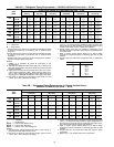
10. See Table 1 for rigging center of gravity (Dimensions K,L,X,Y). See Table 2A
and 2B for A-D corner weights.
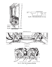
Fig. 5 — Dimensions — Unit 38AH124
8