


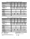
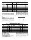
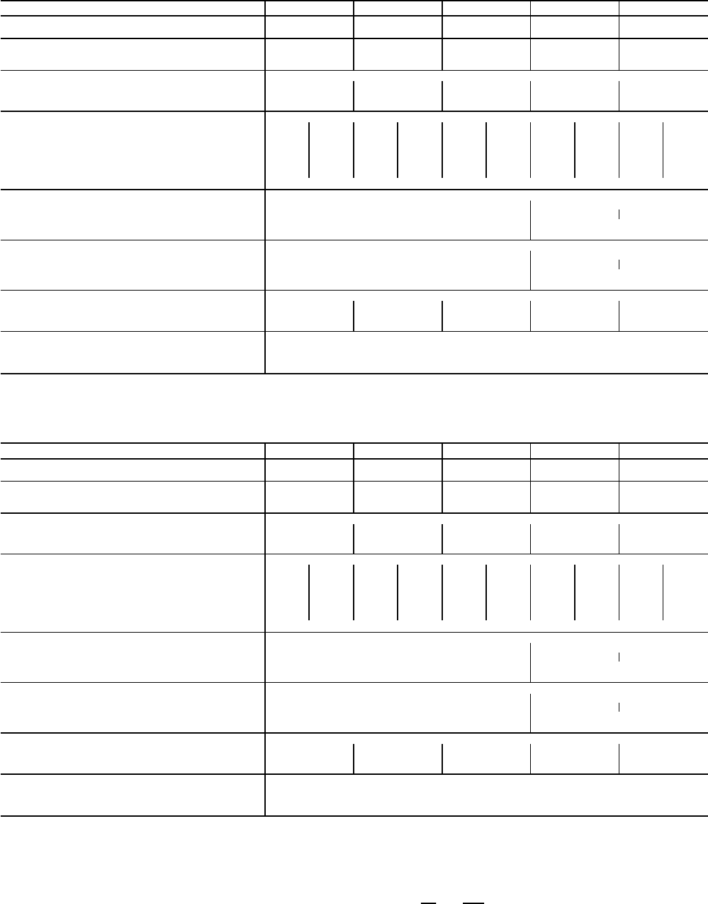
Table 3A — Units 38AH044-084 Physical Data — 50/60 Hz (English)
38AH 044 054 064 074 084
OPERATING WEIGHT WITH Cu-Al 3259 3309 3565 3812 4057
REFRIGERANT (Approx) — Lb Cu-Cu 3547 3597 3998 4229 4735
SHIP WEIGHT WITH COIL PROTECTION ONLY
(Approx) — Lb Cu-Al 3250 3290 3530 3780 4000
Cu-Cu 3538 3578 3963 4197 4678
TYPICAL OPERATING REFRIGERANT R-22
Charge (Approx) — Lb 62 72 88 104 130
Qty of Circuits Std 22222
Opt 11111
COMPRESSOR Type...Rpm Reciprocating Semi-Hermetic...1750 @ 60 Hz; 1458 @ 50 Hz
(Qty Cylinder) Compressor* Std (4) A1 (4) B1 (4) A1 (6) B1 (6) A1 (6) B1 (6) A1 (6) B1 (6)A1 (6) B1
Model No. 06E Std 250 250 250 265 265 275 275 299 299 299
(Qty Cylinder) Compressor* Opt (4) A1 (4)A2 (6)A1 (4)A2 (6)A1 (6)A2 (6)A1 (6)A2 (6)A1 (6) A2
Model No. 06E Opt 250 250 265 250 275 265 299 275 299 299
Oil Charge (Pt) Std 17 17 17 21 21 21 21 19 19 19
Opt 17 17 21 17 21 21 19 21 19 19
Capacity Control Steps† 4
CONDENSER FANS (6 Blade) — 60 Hz
Qty...Dia (in.) 4...30 6...30
Airflow (Cfm) 35,000 52,000 51,000
Speed (Rpm) 1140 1140
Total Power (kW) 6.2 9.3
CONDENSER FANS (6 Blade) — 50 Hz
Qty...Dia (in.) 4...30 6...30
Airflow (Cfm) 35,000 52,000 51,000
Speed (Rpm) 950 950
Total Power (kW) 6.2 9.3
CONDENSER COIL Enhanced Copper Tubes, Aluminum Lanced Fin
Rows...Fins per in. 2...17 2...17 3...17 2...19 3...17
Face Area (sq ft) 80.5 80.5 80.5 116.7 116.7
Storage Capacity (Lb per Circuit) at 120 F 35 35 55 55 80
CONNECTIONS
Suction, ODF (in.)** 2
1
⁄
8
Liquid, ODF (in.)**
7
⁄
8
Hot Gas Bypass, ODF (in.)
5
⁄
8
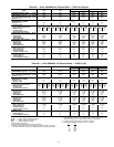
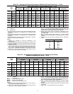
Table 3B — Units 38AH044-084 Physical Data — 50/60 Hz (SI)
38AH 044 054 064 074 084
OPERATING WEIGHT WITH Cu-Al 1478 1501 1617 1729 1840
REFRIGERANT (Approx) — Kg Cu-Cu 1609 1632 1813 1918 2148
SHIP WEIGHT WITH COIL PROTECTION ONLY
(Approx) — Kg Cu-Al 1474 1492 1601 1715 1814
Cu-Cu 1605 1623 1798 1904 2122
TYPICAL OPERATING REFRIGERANT R-22
CHARGE (Approx) — Kg 28.1 32.7 39.9 47.2 58.9
Qty of Circuits Std 22222
Opt 11111
COMPRESSOR Type...R/s Reciprocating Semi-Hermetic...29.2 @ 60 Hz; 24.3 @ 50 Hz
(Qty Cylinder) Compressor* Std (4) A1 (4) B1 (4) A1 (6) B1 (6) A1 (6) B1 (6) A1 (6) B1 (6)A1 (6) B1
Model No. 06E Std 250 250 250 265 265 275 275 299 299 299
(Qty) Cylinder) Compressor* Opt (4) A1 (4)A2 (6)A1 (4) A2 (6)A1 (6)A2 (6)A1 (6)A2 (6)A1 (6)A2
Model No. 06E Opt 250 250 265 250 275 265 299 275 299 299
Oil Charge (L) Std 8.0 8.0 8.0 9.9 9.9 9.9 9.9 9.0 9.0 9.0
Opt 8.0 8.0 9.9 8.0 9.9 9.9 9.0 9.9 9.0 9.0
Capacity Control Steps† 4
CONDENSER FANS (6 Blade) — 50 Hz
Qty...Dia (mm) 4...762 6...762
Airflow (L/s) 16,500 24,500 24,100
Speed (R/s) 15.8 15.8
Total Power (kW) 6.2 9.3
CONDENSER FANS (6 Blade) — 60 Hz
Qty...Dia (mm) 4...762 6...762
Airflow (L/s) 16,500 24,500 24,100
Speed (R/s) 19.0 19.0
Total Power (kW) 6.2 9.3
CONDENSER COIL Enhanced Copper Tubes, Aluminum Lanced Fin
Rows...Fins per m 2...669 2...669 3...669 2...782 3...669
Face Area (sq m) 7.48 7.48 7.48 10.84 10.84
Storage Capacity (Kg per Circuit) at 48.9 C 16 16 25 25 36
CONNECTIONS
Suction, ODF (in.)** 2
1
⁄
8
Liquid, ODF (in.)**
7
⁄
8
Hot Gas Bypass, ODF (in.)
5
⁄
8
LEGEND
Cu-Al — Copper tubes with aluminum fins
Cu-Cu — Copper tubes with copper fins
ODF — Outside Diameter, Female
Opt — Optional Single-Circuit Units
Std — Standard Dual-Circuit Units
*Compressor A1 is lead on standard and optional single-circuit units.
†Capacity control steps listed are for constant-volume units with no accesso-
ries. Refer to Table 19A or 19B, page 48, for additional system capacity
information.
**For single-circuit units, suction ODF is 2
5
⁄
8
in. (66.7 mm) and liquid ODF is
1
1
⁄
8
in. (28.6 mm). Single circuits have a factory-installed manifold; no
field modification is required.
NOTES:
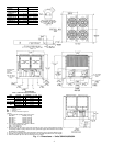
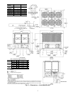
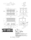
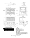
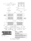
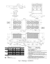
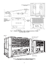
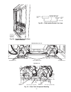
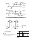
1. Certified dimensional drawings available on request.
2. Equivalent connection values in mm are as follows:
in. mm
5
⁄
8
15.9
7
⁄
8
22.2
2
1
⁄
8
54.0
10