


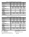
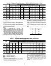
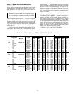

Table 6A — Refrigerant Piping Requirements — 38AH044-104 Dual-Circuit Units — 60 Hz
UNIT
38AH
TOTAL LINEAR LENGTH OF INTERCONNECTING PIPE — FT (M)
15-25
(4.6-7.6)
25-50
(7.6-15.2)
50-75
(15.2-22.9)
75-100
(22.9-30.5)
100-150
(30.5-45.7)
150-200
(45.7-61.0)
LSLSL S L S L S L S
044
Ckt A
5
⁄
8
1
5
⁄
8
7
⁄
8
1
5
⁄
8
7
⁄
8
2
1
⁄
8
7
⁄
8
2
1
⁄
8
7
⁄
8
2
1
⁄
8
7
⁄
8
2
1
⁄
8
Ckt B
5
⁄
8
1
5
⁄
8
7
⁄
8
1
5
⁄
8
7
⁄
8
2
1
⁄
8
7
⁄
8
2
1
⁄
8
7
⁄
8
2
1
⁄
8
7
⁄
8
2
1
⁄
8
054
Ckt A
5
⁄
8
1
5
⁄
8
7
⁄
8
1
5
⁄
8
7
⁄
8
2
1
⁄
8
7
⁄
8
2
1
⁄
8
7
⁄
8
2
1
⁄
8
7
⁄
8
2
1
⁄
8
Ckt B
7
⁄
8
1
5
⁄
8
7
⁄
8
2
1
⁄
8
7
⁄
8
2
1
⁄
8
1
1
⁄
8
2
1
⁄
8
1
1
⁄
8
2
1
⁄
8
1
1
⁄
8
2
5
⁄
8
*
064
Ckt A
7
⁄
8
1
5
⁄
8
7
⁄
8
2
1
⁄
8
7
⁄
8
2
1
⁄
8
7
⁄
8
2
1
⁄
8
1
1
⁄
8
2
1
⁄
8
1
1
⁄
8
2
5
⁄
8
†
Ckt B
7
⁄
8
2
1
⁄
8
7
⁄
8
2
1
⁄
8
7
⁄
8
2
1
⁄
8
1
1
⁄
8
2
1
⁄
8
1
1
⁄
8
2
5
⁄
8
1
1
⁄
8
2
5
⁄
8
074
Ckt A
7
⁄
8
2
1
⁄
8
7
⁄
8
2
1
⁄
8
7
⁄
8
2
1
⁄
8
1
1
⁄
8
2
1
⁄
8
1
1
⁄
8
2
5
⁄
8
†1
1
⁄
8
2
5
⁄
8
†
Ckt B
7
⁄
8
2
1
⁄
8
1
1
⁄
8
2
1
⁄
8
1
1
⁄
8
2
1
⁄
8
1
1
⁄
8
2
5
⁄
8
1
3
⁄
8
2
5
⁄
8
1
3
⁄
8
2
5
⁄
8
084
Ckt A
7
⁄
8
2
1
⁄
8
1
1
⁄
8
2
1
⁄
8
1
1
⁄
8
2
1
⁄
8
1
1
⁄
8
2
5
⁄
8
†1
3
⁄
8
2
5
⁄
8
†1
3
⁄
8
2
5
⁄
8
†
Ckt B
7
⁄
8
2
1
⁄
8
1
1
⁄
8
2
1
⁄
8
1
1
⁄
8
2
1
⁄
8
1
1
⁄
8
2
5
⁄
8
1
3
⁄
8
2
5
⁄
8
1
3
⁄
8
2
5
⁄
8
094
Ckt A
7
⁄
8
2
1
⁄
8
1
1
⁄
8
2
1
⁄
8
1
1
⁄
8
2
5
⁄
8
†1
1
⁄
8
2
5
⁄
8
†1
3
⁄
8
2
5
⁄
8
†1
3
⁄
8
3
1
⁄
8
**
Ckt B
7
⁄
8
2
1
⁄
8
7
⁄
8
2
1
⁄
8
1
1
⁄
8
2
1
⁄
8
1
1
⁄
8
2
5
⁄
8
1
1
⁄
8
2
5
⁄
8
1
3
⁄
8
2
5
⁄
8
104
Ckt A
7
⁄
8
2
1
⁄
8
1
1
⁄
8
2
1
⁄
8
1
1
⁄
8
2
5
⁄
8
†1
1
⁄
8
2
5
⁄
8
†1
3
⁄
8
2
5
⁄
8
†1
3
⁄
8
3
1
⁄
8
**
Ckt B
7
⁄
8
2
1
⁄
8
1
1
⁄
8
2
1
⁄
8
1
1
⁄
8
2
5
⁄
8
1
1
⁄
8
2
5
⁄
8
1
3
⁄
8
3
1
⁄
8
** 1
3
⁄
8
3
1
⁄
8
**
LEGEND
L—Liquid Line
S—Suction Line
*Double suction riser required on units with field installed unloader
on circuit B compressor if condensing unit is elevated above
evaporator.
†Double suction riser required on units with field installed unloader
on circuit B compressor if condensing unit is elevated above
evaporator.
**Double suction riser required on all unit configurations if condens-
ing unit is elevated above evaporator.
NOTES:
1. Addition of 2 unloaders to circuit B compressor is not
recommended.
2. 38AH094 and 38AH104 piping sizes apply only to factory sup-
plied unit configurations. They do NOT take into account any field
installed unloaders.
3. Piping sizes are based on unit operation above 40 F (4.4 C) satu-
rated suction temperature (SST). When operating below 40 F
(4.4 C),refer to CarrierSystem DesignManual, E20-IIா pipingde-
sign program, or ASHRAE Handbook to select proper line sizes.
4. Pipe sizes are based on the total linear length shown for each
column, plus a 50% allowance for fittings.
5. Suctionandliquid linesizing isbased onpressure dropequivalent
to 2 F (1.1 C) at nominal rating conditions. Higher pressure drop
design criteria may allow selection of smaller pipe sizes, but at a
penalty of decreased system capacity and efficiency.
6. Double suction risers may be required if condensing unit is
elevated above the evaporator. See footnotes and double suction
riser table below.
7. Refer to Carrier System Design Manual or to E20-II design
programs for further information on selecting pipe sizes for split
systems.
8. All pipe sizes are OD inches. Equivalent sizes in millimeters
follow:
in. mm
5
⁄
8
15.9
7
⁄
8
22.2
1
1
⁄
8
28.6
1
3
⁄
8
34.9
1
5
⁄
8
41.3
2
1
⁄
8
54.0
2
5
⁄
8
66.7
3
1
⁄
8
79.4
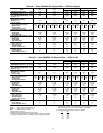
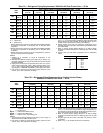
Table 6B — Refrigerant Piping Requirements for Double Suction Risers,
38AH054-104 Dual-Circuit Units — 60 Hz
UNIT
38AH
TOTAL LINEAR LENGTH OF INTERCONNECTING PIPE — FT (M)
50-75
(15.2-22.9)
75-100
(22.9-30.5)
100-150
(30.5-45.7)
150-200
(45.7-61.0)
ABCABCABCABC
054
Ckt A ————————————
Ckt B —————————1
5
⁄
8
2
1
⁄
8
2
5
⁄
8
064
Ckt A —————————1
5
⁄
8
2
1
⁄
8
2
5
⁄
8
Ckt B ————————————
074
Ckt A ——————1
5
⁄
8
2
1
⁄
8
2
5
⁄
8
1
5
⁄
8
2
1
⁄
8
2
5
⁄
8
Ckt B ————————————
084
Ckt A ———1
5
⁄
8
2
1
⁄
8
2
5
⁄
8
1
5
⁄
8
2
1
⁄
8
2
5
⁄
8
1
5
⁄
8
2
1
⁄
8
2
5
⁄
8
Ckt B ————————————
094
Ckt A 1
5
⁄
8
2
1
⁄
8
2
5
⁄
8
1
5
⁄
8
2
1
⁄
8
2
5
⁄
8
1
5
⁄
8
2
1
⁄
8
2
5
⁄
8
1
5
⁄
8
2
5
⁄
8
3
1
⁄
8
Ckt B ————————————
104
Ckt A 1
3
⁄
8
2
1
⁄
8
2
5
⁄
8
1
3
⁄
8
2
1
⁄
8
2
5
⁄
8
1
3
⁄
8
2
1
⁄
8
2
5
⁄
8
1
5
⁄
8
2
5
⁄
8
3
1
⁄
8
Ckt B ——————1
3
⁄
8
2
5
⁄
8
3
1
⁄
8
1
5
⁄
8
2
5
⁄
8
3
1
⁄
8
LEGEND
——Not Required
Pipe A — Suction Riser Without Trap
Pipe B — Suction Riser With Trap
Pipe C — Suction Line to Condensing Unit
NOTES:
1. See Refrigerant Piping Requirements table at top of page to
determine need for double suction risers.
2. Pipe sizes are based on the total linear length, shown for each
column, plus a 50% allowance for fittings.
3. Suctionandliquid linesizing isbased onpressure dropequivalent
to 2F (1.1C) atnominal ratingconditions. Higherdesign pressure
dropcriteria mayallow selectionof smallerpipesizes butat apen-
alty of decreased system capacity and efficiency.
4. Refer to Carrier System Design Manual or to E20-II design
programs for further information on selecting pipe sizes for split
systems.
5. All pipe sizes are OD inches. See Table 6A notes for metric
equivalents.
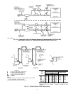
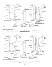
6. Refer to Fig. 13 for double suction riser construction.
16