


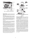

Compressor Removal — Access to the pump end
of the compressor is from the compressor side of the unit.
Access to the motor end of the compressor is from the inside
of the unit. All compressors can be removed from the com-
pressor side of the unit.
IMPORTANT:All compressor mounting hardware and
support brackets removed during servicing must be re-
installed prior to start-up.
1. Disconnect power to unit; lockout power to compressor.
2. Close suction and discharge service valves.
3. Relieve refrigerant pressure into a refrigerant recovery
system.
4. Remove:
a. Fan-cycling pressure switch (FCPS)
b. High-pressure switch
c. Low-pressure switch
d. Oil-pressure switch
e. Discharge gas temperature switch.
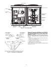
5. Disconnect power wires at terminal box and disconnect
conduit.
6. Disconnect wires from crankcase heater.
7. Disconnect service valves from compressor.
NOTE: On 38AH044-084 optional single-circuit units and
units with 2 compressors per circuit, disconnect both oil
equalizer lines located on the motor barrel and on the oil
pump sump.
8. Units 38AH044-084, 124, and 134:
a. Remove 4 large screws securing compressor mount-
ing pan to unit base rail.
b. Slide compressor (on mounting pan) to outside of unit
frame; support and/or lower to ground.
c. Unbolt compressor from mounting pan and remove.
9. Units 38AH094, 104:
a. Remove 4 large screws securing compressor to the com-
pressor rails.
b. Lift compressor off mounting bolts and remove.
Compressor Replacement — Perform the following:
1. Reverse procedure in Compressor Removal section to end
of Step 4.
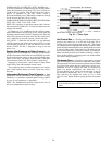
2. Reinstall service valves and safety switches, and tighten
to torques as listed:
Torque
Compressor(s)
Tighten discharge valves to —
20-25 ft-lbs ( 27- 34 N-m) 06E-250
80-90 ft-lbs (109-122 N-m) 06E-265,275,299
Tighten suction valves to —
80- 90 ft-lbs (109-122 N-m) 06E-250
90-120 ft-lbs (122-163 N-m) 06E-265,275,299
Tighten the following fittings as specified —
60 ft-lbs (81 N-m) Discharge Gas Thermostat
120 in.-lbs (13.5 N-m) High-Pressure Switch, Fan-
Cycling Pressure Switch
120 in.-lbs (13.5 N-m) Low-Pressure Switch
3. Leak-check and evacuate system, reclaim refrigerant.
4. Recharge system per pre-start-up and start-up sequences.
Recheck oil levels.
5. Energize crankcase heater for 24 hours prior to restart of
system.
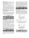
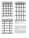
OIL CHARGE — (Refer to Table 3A, 3B, 4A, or 4B.) All
units are factory charged with oil. Acceptable oil level for
each compressor is from
1
⁄
8
to
1
⁄
3
of sight glass (see Fig. 29,
page 38).
When additional oil or a complete charge is required, use
only Carrier-approved compressor oil.
Approved oils are:
Petroleum Specialties, Inc. — Cryol 150A (factory oil charge)
Texaco, Inc. — Capella WF-32-150
Witco Chemical Co. — Suniso 3GS
COMPRESSOR
OIL REQUIRED
Pts L
06E-250 17 8.0
06E-265 21 9.9
06E-275 21 9.9
06E-299 19 9.0
Do not reuse drained oil, and do not use any oil that has
been exposed to atmosphere.
Adjust oil level in accordance with Start-Up, Preliminary
Oil Charge, page 38.
52