


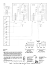
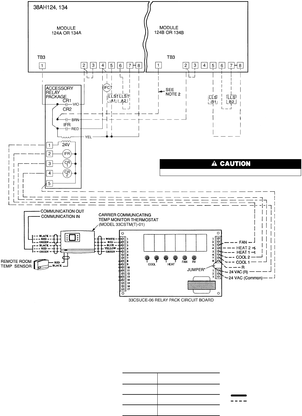
LEGEND
AWG — American Wire Gage
C—Compressor Contactor
CCPS — Capacity Control Pressure
Switch
CR — Control Relay
HD — Heating Device
IFC — Indoor-Fan Contactor
IFR — Indoor-Fan Relay
kcmil — Thousand Circular Mils
LLS — Liquid Line Solenoid
NEC — National Electrical Code
(U.S.A. Standard)
R—Heating Relay (field-
supplied 24-v sealed coil,
10 va maximum rating)
RV — Reversing Valve
SDR — Solenoid Drop Relay
TB — Terminal Block
TR — Timer Relay
Factory Wiring
Field Wiring
*Jumper removed only when separate 24-v trans-
formerpowersourceisusedtopowerthe33CSUCE-06
relay pack.
†Field-supplied.
Internal 33CSUCE-06 relay contacts are rated for 1 amp/24 vac.
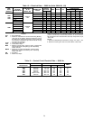
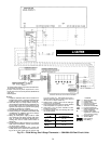
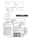
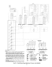
Fig. 23 — Field Wiring, One 2-Stage Thermostat — Units 38AH124 and 134
NOTES:
1. LiquidlinesolenoidvalvesLLS-A1andA2areused
for solenoid drop on Module 124A or 134A on cir-
cuit A. Liquid line solenoid valves LLS-B1 and B2
areusedforsolenoiddropforModule124Bor134B.
Solenoid drop is a safety feature which prevents
refrigerant migration to the compressor during
the OFF cycle. It is recommended on all systems
and required on systems where piping exceeds
75 ft (22.9 m) in length.
2. DisconnectblackwirefromCR2terminal6;caploose
end and secure. Connect new field-supplied wire
from CR2 terminal 6 to TB3 terminal 1 on module
124B or 134B.
3. The 33CSUCE-06 relay pack requires 10 va.
4. FactorywiringisinaccordancewithNEC;fieldmodi-
fications or additions must be in compliance with
all applicable codes.
5. Wiring for field power supply must be rated 75 C
minimum. Use copper, copper-clad aluminum, or
aluminumconductors.Maximumincomingwire size
for each terminal block is 500 kcmil.
6. Terminal blocks (TB3) are for external field control
connections. Control connections mustbe Class 1
wiring.
7. Field-supplied components (IFC, LLS-A1,A2, and
LLS-B1,B2) must have a maximum sealed coil
rating of 30 va each (0.25 amp at 120 vac and
0.13 amp at 230 vac). Thermostats must have a
minimum pilot duty rating of 300 va (2.5 amps at
120 vac).
8. Replacement of factory wires must be with type
105 C wire or its equivalent.
9. Field-supplied liquid line solenoid valves installed
at the evaporator are required on all units.
10. Units have 175 va of power available for field-
installed accessories.
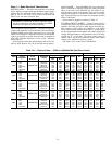
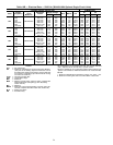
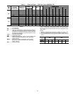
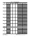
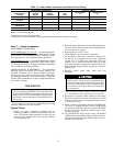
11. To minimize voltage drop, the following wire sizes
are recommended:
LENGTH —
Ft (M)
INSULATED WIRE — AWG
(35 C Minimum)
Up to 50
(15.2)
No. 18
50-75
(15.2-22.9)
No. 16
More Than 75
(22.9)
No. 14
31