


NOTE: Use only Carrier approved compressor oil. Ap-
proved sources are: Petroleum Specialties Inc. (Cryol 150A),
Texaco, Inc. (Capella WF-32-150), and Witco Chemical Co.
(Suniso 3GS). Do not reuse oil that has been drained out, or
oil that has been exposed to atmosphere.
REMOVE OIL — Pump down compressor to 2 psig
(14 kPag). Loosen the
1
⁄
4
-in. (6.4-mm) pipe plug at the com-
pressor base and allow the oil to seep out past the threads of
the plug.
NOTE: The crankcase will be slightly pressurized. Do not
remove the plug, or the entire oil charge will be lost.
Small amounts of oil can be removed through the oil pump
discharge connection while the compressor is running.
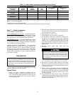
Preliminary Charge — Refer to GTAC II (General Train-
ing Air Conditioning), Module 5, Charging, Recovery,
Recycling, and Reclamation for charging procedures. Using
the liquid charging method and charging by weight proce-
dure, charge each circuit with the amount of R-22 listed in
Table 3A, 3B, 4A, or 4B.
Never charge liquid into the low-pressure side of sys-
tem. Do not overcharge. During charging or removal of
refrigerant, be sure indoor-fan system is operating.
Start Unit — The field disconnect is closed, the fan cir-
cuit breaker is closed, and the space thermostats are set above
ambient so that there is no demand for cooling. Only the
crankcase heaters are energized.
Close the compressor circuit breakers and then reset both
space thermostats below ambient so that a call for stage one
cooling is ensured. Lead refrigeration circuit ther-
mostat TC1 must be set to call for cooling at a lower tem-
perature than lag refrigeration circuit thermostat TC2.
See Table 16 for lead/lag circuits on all units. Now set TC2
for cooling.
NOTE: Do not use circuit breakers to start and stop the com-
pressor except in an emergency.
38AH044-084 DUAL-CIRCUIT UNITS — Start-up of lead
compressor A1 (Table 16) will be delayed from 12 seconds
to 5
1
⁄
2
minutes from the time the call for cooling is initiated
by TC1.After the lead compressor starts, close the TC2 ther-
mostat to start lag circuit compressor B1. Compressor B1
will start a minimum of 60 seconds after thermostat TC2 is
closed.
38AH044-084 OPTIONAL SINGLE CIRCUIT UNITS —
Start-up of lead compressor A1 (Table 16) is delayed from
12 seconds to 5
1
⁄
2
minutes from the time the call for cooling
is initiated by TC1. Closure of TC2 will actuate LLS-A2.
Lag compressorA2 is controlled by D-D2 timer contacts and
capacity control pressure switches (CCPSs) which monitor
compressor suction pressure. The lag compressor starts ap-
proximately 2
1
⁄
2
minutes after the lead compressor starts if
the suction pressure is above the CCPS set point.
38AH094,104 UNITS — Start-up of lead circuit A,
compressor A1 (Table 16) is delayed from 12 seconds to
5
1
⁄
2
minutes from the time the call for cooling is initiated.
After lead circuit A, compressor A1 starts, close refrig-
eration circuit thermostat TC2 to start lag circuit B, lead
compressor B1. Start-up of compressor B1 is delayed from
12 seconds to 5
1
⁄
2
minutes. (Circuit B of unit 38AH094 has
only one compressor.)
Each circuit’s lead compressor start-up is controlled by
the unit control timer. The circuit’s lag compressor start-up
is controlled by the D-D2 timer contacts and capacity
control pressure switches (CCPSs) which monitor compres-
sor suction pressure. The circuit’s lag compressor will start
approximately 2
1
⁄
2
minutes after a call for cooling if com-
pressor pressure is above CCPS set point.
38AH124,134 UNITS — Start-up of the lead circuit
(Module 124A or 134A) lead compressor A1 (Table 16) is
delayed from 12 seconds to 5
1
⁄
2
minutes from the time the
call for cooling is initiated by TC1. Lag compressor A2 is
controlled by D-D2 timer contacts and capacity control pres-
sure switches (CCPSs) which monitor compressor suction
pressure. The lag compressor starts approximately 2
1
⁄
2
min-
utes after the lead compressor starts if the suction pressure
is above the CCPS set point.
After the lead circuit (Module 124A or 134A) lead com-
pressorA1 (Table 16) starts, close the TC2 thermostat to start
the lag circuit (Module 124B or 134B) lead compressor (A1).
Lag circuit compressor A1 start-up is delayed from 12 sec-
onds to 5
1
⁄
2
minutes from the time the call for cooling is
initiated by TC2. Lag compressor A2 is controlled by D-D2
timer contacts and CCPSs which monitor compressor suc-
tion pressure. Lag compressor A2 starts approximately 2
1
⁄
2
minutes after lead compressor A1 starts if the suction pres-
sure is above the CCPS set point.
Adjust Refrigerant Charge
Never charge liquid into the low-pressure side of sys-
tem. Do not overcharge. During charging or removal of
refrigerant, be sure indoor-fan system is operating.
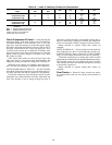
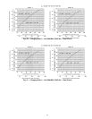
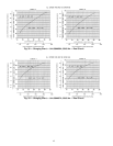
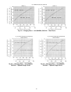
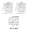
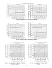
With all fans operating, and all compressors on the cir-
cuit being serviced operating at full capacity, adjust the
refrigerant charge in accordance with the unit charging charts
located on the inside of the control box doors and in
Fig. 30-43. Charge vapor into compressor low-side service
port located above oil pump crankshaft housing. Measure
pressure at the liquid line service valve,making sure a Schrader
depressor is used if required. Also, measure liquid line tem-
perature as close to the liquid service valve as possible. Add
charge until the pressure and temperature conditions of the
charging chart curve are met. If liquid pressure and tempera-
ture point fall above curve, add charge. If liquid pressure
and temperature point fall below curve, reduce the charge
until the conditions match the curve.
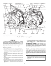
If the sight glass at location A (Fig. 11 and 12) is cloudy,
check refrigerant charge again. Ensure all fans and com-
pressors on the circuit being serviced are operating. Also
ensure maximum allowable liquid lift has not been
exceeded.
If the sight glass at location A is clear and the sight
glass at location B is cloudy, a restriction exists in the
line between the 2 sight glasses. Check for a plugged filter
drier or partially open solenoid valve. Replace or repair, as
needed.
39