


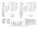
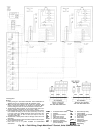

LEGEND
AWG — American Wire Gage
CR — Control Relay
HD — Heating Device
IFC — Indoor-Fan Contactor
IFR — Indoor-Fan Relay
kcmil — Thousand Circular Mils
LLS — Liquid Line Solenoid
NEC — National Electrical Code
(U.S.A. Standard)
R—Heating Relay (field-
supplied 24-v sealed coil,
10 va maximum rating)
RV — Reversing Valve
TB — Terminal Block
Factory Wiring
Field Wiring
*Tocontrolheatingdeviceandprovideautomaticindoor-
fan operation on heating.
†Jumper removed only when separate 24-v trans-
formerpowersourceisusedtopowerthe33CSUCE-06
relay pack.
**Field-supplied.
Internal 33CSUCE-06 relay contacts are rated for 1 amp/24 vac.
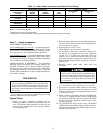
NOTES:
1. Liquid line solenoid valve LLS-A1 is used for solenoid drop
on circuit A. Liquid line solenoid valve LLS-B1 is used for
solenoid drop for circuit B.
2. Solenoid drop is a safety feature which prevents refrigerant
migration to the compressor during the OFF cycle. It is rec-
ommended on all systems and required on systems where
piping exceeds 75 ft (22.9 m) in length.
3. The 33CSUCE-06 relay pack requires 10 va.
4. Factory wiring is in accordance with NEC; field modifications
or additions must be in compliance with all applicable codes.
5. Wiring for field power supply must be rated 75 C mini-
mum. Use copper, copper-clad aluminum, or aluminum con-
ductors. Maximumincoming wiresize foreach terminalblock
is 500 kcmil.
6. Terminalblocksareforexternalfieldcontrolconnections.Con-
trol connections must be Class 1 wiring.
7. Field-supplied components (IFC, LLS-A1, and LLS-B1) must
have a maximum sealed coil rating of 30 va each (0.25 amp
at120 vacand0.13 ampat230 vac).Thermostatsmusthave
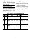
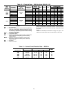
a minimum pilot duty rating as follows:
38AH
VA
(Ea Stage)
AMPS VAC
094 275
2.29 120
1.15 240
104 325
2.70 120
1.35 240
8. Replacement of factory wires must be with
type 105 C wire or its equivalent.
9. Field-suppliedliquidlinesolenoid valvesin-
stalled atthe evaporator are requiredon all
units.
10. Units38AH094has140vaandunit38AH104
has 130 va of power available for field-
installed accessories.
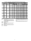
11. Tominimizevoltage drop,thefollowing wire
sizes are recommended:
LENGTH —
Ft (M)
INSULATED WIRE —
AWG
(35 C Minimum)
Up to 50
(15.2)
No. 18
50-75
(15.2-22.9)
No. 16
More Than 75
(22.9)
No. 14
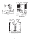
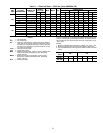
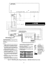
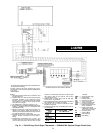
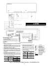
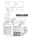
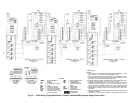
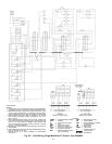
Fig. 22 — Field Wiring, One 2-Stage Thermostat — Units 38AH094 and 104
30