


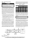
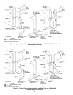
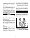
Units 38AH124 and 134 Piping Kit Connections — The
38AH124 and 134 units are delivered with a factory-
supplied suction and liquid piping kit for installation in the
24-in. (610-mm) service space between the 2 unit modules.
The piping kit allows for a common unit side piping con-
nection from the indoor unit to each of the condensing unit
refrigeration circuits. Fittings are provided and shipped in
the control box.
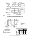
Remove the copper tubes from Module 124Aor 134Acom-
pressor rails. Save the pipe clamps for later use. Cut the
2
5
⁄
8
-in. (67-mm) suction tube into 2 pieces: 28 in. (711 mm)
and 67 in. (1702 mm). Connect the 2 formed 1
1
⁄
8
-in.
(29-mm) tubes to the liquid line connection at the liquid valve.
See Fig. 16.
NOTE: Piping kit is designed to allow air handler connec-
tions to project from either side of the service space.
To prepare condensing unit modules for piping connec-
tion, refer to beginning paragraphs of Step 3 — Make
Refrigeration Piping Connections, page 14.
Two 2
5
⁄
8
-in. (67-mm) and one 1
1
⁄
8
-in. (29-mm) elbows are
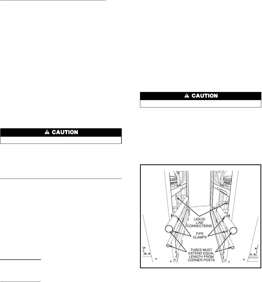
supplied for piping connections. Fit tubing to ensure proper
installation. All tubes should have equal lengths projecting
beyond unit corner posts. See Fig. 16. Ensure suction tube
is level for oil return requirements.
Protect liquid valves from the heat of brazing.
Braze the piping connections.
Level the tubes and clamp to the corner posts with factory-
supplied self-drilling screws and pipe clamps removed from
Module 124A or 134A during piping kit removal.
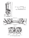
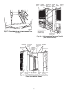
Units 38AH124 and 134 Sheet Metal Trim Kit Installation
— After the units are in place and the piping kit is installed,
install the sheet metal trim kit.
NOTE: Install sheet metal trim kit before connection to air
handler tubing in case the modules must be repositioned to
accommodate the sheet metal installation.
Remove two 43-in. (1092 mm) base rail trim pieces from
Module 124A or 134A base rail. Remove the 3 corner post
bolts from the bottom of each corner post at the service space.
Align the base rail trim piece holes over the bolt holes in the
corner rails. See Fig. 17. Reinsert corner post bolts through
the trim piece into the corner posts.
Attach Top Cover — To attach top cover, proceed as
follows:
For Unit 38AH124, remove screws A from top of each of
4 corner posts at service space. See Fig. 18. Place cover on
top of service space and align top cover slots with corner
post screw holes. Reinsert screws A.
For Unit 38AH134, remove screws A from top of each cor-
ner post on Module 134A and screws B from top of each
corner post on Module 134B. See Fig. 18. Top cover is in
2 pieces: one vertical piece and one horizontal piece. Slide
vertical top cover partly under Module 134B end cover flange;
align holes and reinsert screws B. Place horizontal cover on
top of Module 134A end cover with opposite side resting on
the horizontal flange of the installed Module B vertical top
cover piece. Align holes on flange and top cover. Reinsert
screwsAthrough the top cover holes into the end cover. From
within the service space, insert supplied screws up through
the flange and horizontal cover to make a secure connection
between the horizontal and vertical cover pieces.
Insert supplied screws into each of the 2 holes in the ver-
tical side flange of the top cover at each end of the service
space.
Attach Side Panels — Insert side panels at the ends of the
service space and hook side panel flange over the 2 screws
previously inserted in the top cover flange. Fasten panels to
the corner posts with supplied self-drilling screws, 3 per side.
See Fig. 19.
Connect Tubing from Evaporator to Unit
Protect liquid valves from the heat of brazing.
Braze the liquid and suction lines from the evaporator to
the condensing unit liquid and suction lines. Leak test the
entire system by the pressure method described in the
Carrier Standard Service Techniques Manual, Chapter 1,
Section 1-6. Use R-22 at approximately 25 psig (172 kPa)
backed up with an inert gas to a total pressure not to exceed
245 psig (1689 kPa). If a leak is detected, evacuate and de-
hydrate the system. Follow methods described in the Carrier
Service Manual, Chapter 1, Section 1-7.
NOTES:
1. Ensure suction tube is level for oil return requirements.
2.
Protect liquid valves from heat of brazing.
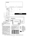
Fig. 16 — Units 38AH124 and 134 with Installed
Piping Kit
21