


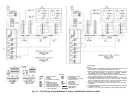
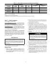

Table 15 — Main Power Connection and Control Circuit Wiring
MAIN POWER CONNECTION CONTROL CIRCUIT
Electrical
Characteristics
(V-Ph-Hz)
Qty
Terminal
Blocks
Qty
Parallel
Conductors*
Max Wire
Size
(kcmil)
Control Power
(V)
Safety Circuit
(V)
208/230-3-60 1 6 500 115† 24
460-3-60
575-3-60
1 3 500 115† 24
230-3-50 1 6 500 230 24
380-3-60
380/415-3-50
1 3 500 230 24
346-3-50 1 3 500 200 24
LEGEND
kcmil — Thousand Circular Mils
*Conductors are from the safety disconnect.
†Control power is accomplished with a step-down transformer where primary voltage is field voltage.
Step 5 — Install Accessories
LOW-AMBIENT OPERATION
Units 38AH044-084, 124, and 134 — If operating tempera-
tures below 55 F (13 C) are expected, Motormaster III fan
motor control is recommended. Refer to separate installa-
tion instructions for low-ambient operation guidelines.
Units 38AH094 and 104 — If operating temperatures below
45 F (7 C) are expected, Motormaster III fan motor control
is recommended. Refer to separate installation instructions
for low-ambient operation guidelines.
MISCELLANEOUS ACCESSORIES — For applications
requiring special accessories, the following packages are
available: condenser coil hail guard package, gage panel,
unloader package, unloader conversion kits, sound reduc-
tion package, condenser coil protective grilles, compressor
security grilles, ModuPanel™ control, and thermostat trans-
former relay package.
PRE-START-UP
IMPORTANT: Before beginning Pre-Start-Up or Start-
Up, review Start-Up Checklist at the back of this pub-
lication. The Checklist assures proper start-up of a unit
and provides a record of unit condition, application re-
quirements, system information, and operation at ini-
tial start-up.
Do not attempt to start the air-conditioning system until
following checks have been completed.
System Check
1. Check all system components, including the air-
handling equipment. Consult manufacturer’s instruc-
tions. If the unit has field-installed accessories, be sure
all are properly installed and wired correctly. Refer to
unit wiring diagrams.
2. Backseat (open) compressor suction and discharge shut-
off valves. Close valves one turn to allow refrigerant pres-
sure to reach the test gages.
3. Open liquid line service valves.
4. Check tightness of all electrical connections.
5. Oil should be visible in the compressor sight glasses.
See Fig. 29. An acceptable oil level in the compressor
is from
1
⁄
8
to
1
⁄
3
of sight glass. Adjust the oil level as
required. No oil should be removed unless the crank-
case heater has been energized for at least 24 hours. See
Preliminary Oil Charge section on page 38, for Carrier-
approved oils.
6. Electrical power source must agree with unit
nameplate.
Crankcase heaters on all units are wired into the
control circuit, so they are always operable as long
as the main power supply disconnect is on (closed),
even if any safety device is open. Compressor heat-
ers must be on for 24 hours prior to the start-up of
any compressor.
7. Crankcase heaters must be firmly locked into compres-
sors, and must be on for 24 hours prior to start-up.
8. Fan motors are 3-phase. Check rotation of fans during
first start-up check. Fan rotation is clockwise as viewed
from top of unit. If fan is not turning clockwise, reverse
2 of the power wires.
9. Check compressor suspension. On units 38AH044-084,
124, and 134, snubber washers (for noise suppression)
can be moved with finger pressure. On units 38AH094
and 104, rails allow compressors to float freely on com-
pressor rail springs.
10. On 38AH074,084 single-circuit units and Module
38AH134B, ensure that the packaging block located be-
tween the oil equalization tube and the compressor cross-
brace has been removed.
37