


38AH044-084 DUAL-CIRCUIT UNITS; 38AH094,104 —
If circuit A operation is insufficient for the cooling require-
ments, the thermostat second stage TC2 closes to bring cir-
cuit B on-line for cooling. This circuit follows the same se-
quence of operation as the lead circuit, except a
60-second time delay relay (TDR) delays compressor start-up
for 60 seconds after the call for cooling.
38AH044-084 OPTIONALSINGLE-CIRCUITUNITS: MOD-
ULES 124A, 124B, 134A, AND 134B
NOTE: This sequence of operation assumes that 2 thermo-
stats control units 38AH124 or 134 with one thermostat con-
trolling each module.
If compressor A1 is insufficient for the cooling require-
ments, the thermostat second stage closes, which opens the
liquid line solenoid valve LLS-A2. Compressor A2 starts only
after D-D2 contacts in the timer close and the suction pres-
sure is sufficient to close the capacity control switches.
ALL UNITS — When the fan switch is set for automatic
(AUTO) operation, the indoor-fan contactor (IFC) is cycled
with the lead compressor. If the fan switch is set for con-
tinuous (CONT), the IFC is energized as long as the unit
power is on.
Restart After Stoppage by Safety Control — The
high-pressure switch, compressor discharge gas thermostats,
and the oil pressure switch must be reset manually by break-
ing the control power supply at any of the following points:
control circuit fuse, fan motor circuit breaker, or the ther-
mostat. Restart follows the Time Guard control delay.
Stoppage by low-pressure switch results in Time Guard
control delay, then unit attempts normal restart.
The compressor motor overcurrent protectors are manual-
reset circuit breakers. Reset of control circuit may also be
necessary.
Independent Refrigerant Circuit Controls — Each
refrigeration circuit is controlled by independent circuitry.
Therefore, it is possible to maintain partial cooling capabil-
ity even if one compressor is inoperable.
NOTE: The 38AH044-084 optional single-circuit units do
not have independent control circuitry.
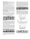
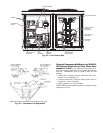
Unit Control Box — (See Fig. 48.) Viewed facing com-
pressors, the control box is at left end of the unit. All in-
coming power enters through the control box. The control
box contains power components and electronic controls. Outer
panels are hinged andlatched for easy opening. Remove screws
to remove inner panels. Outer panels can be held open for
service and inspection by using door retainer on each panel.
Remove bottom pin from door retainer assembly, swing re-
tainer out horizontally, and engage pin in one of the retainer
ears and the hinge assembly.
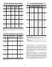
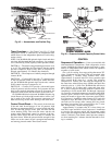
Condenser Fans — Each fan is supported by a formed
wire mount bolted to fan deck and covered with a wire guard.
The exposed end of fan motor shaft is protected from weather
by grease. If fan motor must be removed for service or re-
placement, be sure to regrease fan shaft, and reinstall fan
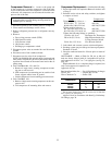
guard. For proper performance, fan should be
7
⁄
8
in.
(22 mm) below top of venturi on the fan deck to top of
the fan hub for 60-Hz units, and
1
⁄
2
in. (13 mm) for 50-Hz
units. (See Fig. 49.) Tighten set screws to 15 ± 1 ft-lbs
(20 ± 1.3 N-m). Figure 49 shows proper position of mounted
fan.
IMPORTANT: Check for proper fan rotation (clock-
wise viewed from above). If necessary to reverse, switch
leads.
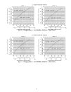
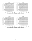
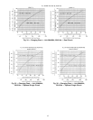
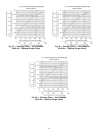
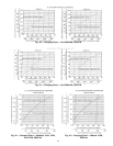
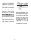
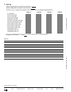
NOTE: Black denotes closed contacts.
Fig. 47 — Timer Cycle
50