


Step 3 — Make Refrigerant Piping
Connections
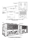
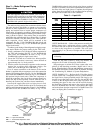
The field-supplied liquid line solenoid valve must be
installed at the evaporator to avoid possible compressor
damage during unit operation. See Fig. 11 (for 38AH044-
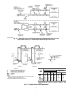
084 dual-circuit and 38AH094-134 units), or Fig. 12 (for
38AH044-084 optional single-circuit units).
The units have large suction lines to minimize friction losses.
The units also have the ability to operate at low capacity.
Because of these capabilities, use special care with suction
piping and suction risers to ensure proper compressor oil
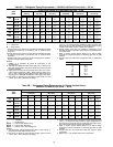
return under all operating conditions. Maximum allowable
vertical separation between the condensing unit and the evapo-
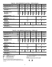
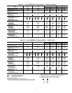
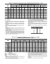
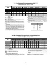
rator is shown in Table 5. Size suction lines in accordance
with Tables 6A or 6B through 9A or 9B and Fig. 13. Mount
liquid line solenoid valve just ahead of the TXVs (thermo-
static expansion valves) which will be mounted at the
evaporator. See Fig. 11 (for 38AH044-084 dual-circuit and
38AH094-134 units) or Fig. 12 (for 38AH044-084 optional
single-circuit units).
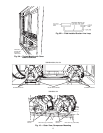
To achieve good mixing of the refrigerant leaving the evapo-
rator suction header for proper sensing by the TXV bulb:
1. Install a minimum of two 90-degree elbows upstream of
the TXV bulb location. See Fig. 14 (for 38AH044-084
dual-circuit and 38AH094-134 units) or Fig. 15 (for
38AH044-084 optional single-circuit units).
2. Locate the TXV bulb on a vertical riser, where possible.
If a horizontal location is necessary, secure the bulb at
approximately the 4 o’clock position.
3. Size the suction line from the evaporator to the common
suction line to achieve high refrigerant velocity. See
Tables 6A or 6B through 9A or 9B and Fig. 13.
If an oil return connection at the bottom of the suction
header is supplied with an evaporator, tee-in this connection
ahead of first mixing elbow. See Fig. 14 (for 38AH044-084
dual-circuit and 38AH094-134 units) or Fig. 15 (for 38AH044-
084 optional single-circuit units). When the compressor is
below the evaporator, the riser at the evaporator should ex-
tend to the top of the evaporator section. After the riser is
installed, the suction line can elbow down immediately.
Install a field-supplied filter drier and sight glasses in each
refrigerant system. Select the filter drier for maximum unit
capacity and minimum pressure drop.Figure 11(for 38AH044-
084 dual-circuit and 38AH094-134 units) or Fig. 12 (for
38AH044-084 optional single-circuit units) shows required
location of solenoid valves and recommended locations for
the filter driers and sight glasses. Complete the refrigerant
piping from the evaporator to the condenser before opening
the liquid and suction lines at the condenser.
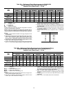
Table 5 — Liquid Lift
UNIT
38AH
MAXIMUM LIQUID LIFT
60 Hz 50 Hz
FtMFtM
044 69 21.0 57.5 17.5
054 75 23.0 75.0 23.0
064 75 23.0 65.0 19.8
074 45 13.7 37.5 11.4
084 75 23.0 75.0 23.0
094 55 16.7 46.0 14.0
104 50 15.2 42.0 12.8
124 75 23.0 65.0 19.8
134 45 13.7 37.5 11.4
UNITS 38AH044-084 — Relieve the pressure caused by the
holding charge into a refrigerant recovery system. Uncap
the suction line and cut the run-around tube at the liquid line
as close to the loop elbow as possible. This will leave
approximately 2 in. (50 mm) of straight tube for liquid line
connection.
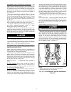
IMPORTANT: Protect the liquid valves from the heat
of brazing.
Leak test the entire system by using soap bubbles and
nitrogen or R-22 with an electronic leak detector.
Purge nitrogen or reclaim R-22 from system after com-
pletion of leak-checking procedure. Repair leak if one is
found. When finished, evacuate and dehydrate system using
the methods described in Carrier GTAC II (General Training
Air Conditioning II), Module 4, System Dehydration.
UNITS 38AH094-134 — Relieve the R-22 holding charge
of each circuit into a refrigerant recovery system. Remove
the liquid line to factory-installed suction line loop by cut-
ting the loop at the liquid valve. (See Fig. 9A and 9B.) Cut
as close to the 90-degree bend in the loop as possible. The
remaining tube piece in the valve will be used for brazing
the liquid line. Unbraze and remove the cap from the liquid
line. For 38AH094 and 104 units, sweat-connect the liquid
and suction lines from the evaporator. For 38AH124 and 134
units, see Piping Kit Connections on page 21.
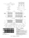
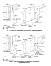
LEGEND
LLS — Liquid Line Solenoid
TXV — Thermostatic Expansion Valve
*Field-Supplied.
Fig. 11 — Required Location of Solenoid Valves and Recommended Filter Drier and
Sight Glass Locations for 38AH044-084 Dual-Circuit and 38AH094-134 Units
14