


START-UP
Compressor crankcase heaters must be on for 24 hours
before start-up. To energize the crankcase heaters, set the
space thermostat above the ambient so there will be no de-
mand for cooling. Close the field disconnect and turn on the
fan circuit breakers. Leave the compressor circuit breakers
off/open. The crankcase heaters are now energized.
Preliminary Checks
1. Ensure that compressor service valves are backseated.
2. Verify that each compressor on units 38AH044-084, 124,
and 134 floats freely on its mounting springs. Verify that
each compressor on units 38AH094 and 104 floats freely
on its rails.
3. Check that electric power supply agrees with unit name-
plate data.
4. Verify that compressor crankcase heaters are securely in
place.
5. Check that compressor crankcase heaters have been on at
least 24 hours.
6. Note that compressor oil level is visible in the sight glass.
7. Recheck for leaks using same procedure as previously out-
lined in Step 3 — Make Refrigerant Piping Connections,
page 14.
8. If any leaks are detected, evacuate and dehydrate as pre-
viously outlined in Step 3 — Make Refrigerant Piping
Connections, page 14.
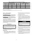
Preliminary Oil Charge — Each compressor is fac-
tory charged with oil (see Table 3A, 3B, 4A, or 4B). When
oil is checked at start-up, it may be necessary to add or re-
move oil to bring it to the proper level. One recommended
oil level adjustment method is as follows:
ADD OIL — Close suction shutoff valve and pump down
crankcase to 2 psig (14 kPa). (Low-pressure cutout must be
jumped.) Wait a few minutes and repeat until pressure re-
mains steady at 2 psig (14 kPa). Remove oil fill plug above
the oil level sight glass, add oil through plug hole, and re-
place plug. Run compressor for 20 minutes and check oil
level.
IMPORTANT: For units with 2 compressors per re-
frigeration circuit, both compressors must be running
to adjust the oil level. Two oil level equalizer lines
between compressors distribute the oil to each
compressor.
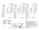
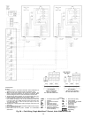
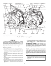
DISCHARGE
GAS THERMOSTAT
CYLINDER
HEADS
OIL PRESSURE SWITCH AND
CAPACITY CONTROL
PRESSURE SWITCH CAPILLARIES
MUFFLER
HIGH-
PRESSURE
SWITCH
FAN CYCLING
PRESSURE SWITCH
DISCHARGE GAS
THERMOSTAT
MOUNTING
SPRING
(HIDDEN)
SIGHT
GLASS
LOW-
PRESSURE
SWITCH
OIL
EQUALIZER
LINE
CRANKCASE
HEATER
RAIL
SIGHT
GLASS
PRESSURE RELIEF
VALVE
NOTE: Units 38AH044-084and 38AH124, 134compressors are pan
mounted.Units 38AH094and 104compressorsare mountedon rails.
Fig. 29 — 06E Compressors, Typical
38