


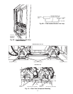

Remove sheet metal cover panels from return-bend end of
Module 124B or 134B. Place Module 124B or 134B in
position. The exposed return-bend ends of each module are
now opposite each other and facing the service space. The
compressors of each module are on opposite sides of the unit.
IMPORTANT: Modules must be placed 24 in.
(610 mm) apart and square relative to each other.
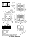
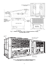
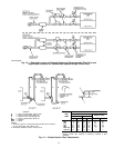
The modules are now in position for piping installa-
tion and final assembly. See Fig. 8. For mounting units on
vibration isolators, a perimeter support channel is required
between the assembled unit and the support isolators. The
perimeter support channel must be sized to support the fully
assembled unit. Do not support modules on individual iso-
lation supports. Support channel, hardware, and fasteners are
field supplied.
When unit is in proper location, level unit and bolt into
position with field-supplied bolts.
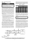
Step 2 — Check Compressor Mounting
UNITS 38AH044-084 — Compressors are mounted on pans
and are held down by 4 bolts during shipment. After unit is
installed, loosen each of these bolts until the snubber washer
can be moved with finger pressure. See Fig. 10.
UNITS 38AH094-134 — Units 38AH094 and 104 compres-
sors are mounted on rails and held down by rail bolts during
shipment. After unit is installed, loosen the rail bolts to al-
low the rails and compressors to float freely on the springs
located under the rails. See Fig. 10.
Units 38AH124 and 134 compressors are mounted on pans
and are held down by 4 bolts during shipment. After unit is
installed, loosen each of these bolts until snubber washer can
be moved with finger pressure. See Fig. 10.
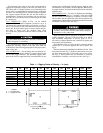
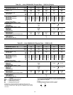
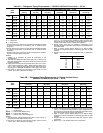
Table 2A — Operational Corner Weights with
Refrigerant Charge (Approximate) — Lb
UNIT
38AH
TOTAL
WEIGHT
OPERATIONAL CORNER WEIGHT
ABCD
044 3259 939 893 695 732
044C 3547 1013 967 765 802
054 3309 964 905 697 742
054C 3597 1034 978 771 814
064 3565 1018 1011 765 771
064C 3998 1125 1117 874 879
074 3812 1146 986 777 903
074C 4229 1272 1059 862 1035
084 4057 1220 1049 827 961
084C 4735 1425 1186 965 1159
094 5088 1114 2192 1182 601
094C 5813 1273 2504 1350 686
104 5435 1240 2138 1302 755
104C 6160 1405 2423 1476 856
MODULE
38AH
124A 3630 1037 1030 779 785
124A-C 4063 1144 1137 889 894
124B 3630 1037 1030 779 785
124B-C 4063 1144 1137 889 894
134A 3630 1037 1030 779 785
134A-C 4063 1144 1137 889 894
134B 3877 1167 997 789 924
134B-C 4294 1293 1080 874 1047
LEGEND
C—Copper Fin Coils
NOTE:Total weightmay differ fromsummation of cornerweights due
to rounding of numerals.
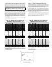
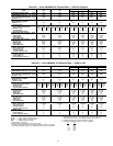
Table 2B — Operational Corner Weights with
Refrigerant Charge (Approximate) — Kg
UNIT
38AH
TOTAL
WEIGHT
OPERATIONAL CORNER WEIGHT
ABCD
044 1478 426 405 316 332
044C 1609 460 438 347 364
054 1501 437 411 316 337
054C 1632 469 444 350 369
064 1617 462 459 347 350
064C 1813 510 508 397 399
074 1729 520 447 352 410
074C 1918 577 481 391 470
084 1840 553 476 375 436
084C 2148 646 538 438 526
094 2308 505 994 536 272
094C 2637 577 1136 612 311
104 2465 562 970 591 342
104C 2794 637 1099 670 388
MODULE
38AH
124A 1647 470 467 353 356
124A-C 1843 519 516 403 405
124B 1647 470 467 353 356
124B-C 1843 519 516 403 405
134A 1647 470 467 353 356
134A-C 1843 519 516 403 405
134B 1759 529 452 358 419
134B-C 1948 587 490 396 475
LEGEND
C—Copper Fin Coils
NOTE:Total weightmay differ fromsummation of cornerweights due
to rounding of numerals.
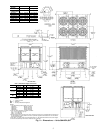
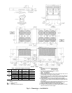
TOP VIEW, TYPICAL
3