


The placement area must be level and strong enough to
support the operating weight of the unit (see Table 3A or
3B). When unit is in proper location, use of mounting holes
in base rails is recommended for securing unit to supporting
structure. For mounting unit on vibration isolators, a perim-
eter support channel between the unit and the isolators is
recommended. Fasteners for mounting unit are field sup-
plied. Be sure to mount unit level to ensure proper oil return
to compressors.
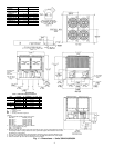
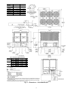
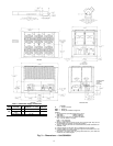
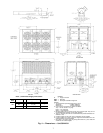
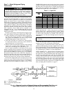
Units 38AH094-134 — Refer to Fig. 3-6 for airflow
clearances. Recommended minimum clearances are 6 ft
(1829 mm) for unrestricted airflow and service on sides of
unit, 5 ft (1524 mm) on ends, and unrestricted clear air space
above unit. Provide ample space to connect liquid and suc-
tion lines to indoor unit. For multiple units, allow
8 ft (2440 mm) separation between units for airflow and
service.
Do not forklift these units unless the unit is attached to
a skid designed for forklifting.
The placement area must be level and strong enough to
support the operating weight of the unit. See Table 4A
or 4B. Refer to the following paragraphs for the proper place-
ment of the unit.
Units 38AH094,104 — For mounting units on vibration iso-
lators, a perimeter support channel is required between the
unit and the support isolators. The perimeter support chan-
nel must be sized to support the fully assembled unit. Do not
support units on individual isolation supports. Support chan-
nel, hardware, and fasteners are field supplied. When unit is
in proper location, level unit and bolt into position with field-
supplied bolts.
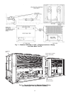
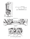
Units 38AH124,134 — For ease of shipment and handling,
unit 38AH124 is shipped as 2 modules (124A and 124B)
and unit 38AH134 is shipped as 2 modules (134A and 134B).
The modules must be connected at the final installation site
with the factory-shipped pipingand sheet metaltrim kit mounted
on Module 124A or 134A. See Fig. 7.
Do not move assembled 38AH124 or 134 units as a single
assembly. Always move modules individually during in-
stallation or at any other time.
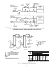
Mark installation site for placement of Modules 124Aand
124B or Modules 134A and 134B. See Table 4A or 4B for
final assembled dimensions. A service space of 24 in.
(610 mm) is required between the 2 modules for piping and
sheet metal trim installation.
Place Module 124A or 134A in position, ensuring that the
control box is at the end opposite the service space. See
Fig. 8.
Remove sheet metal and tubing from Module 124Aor 134A
sheet metal trim kit (Fig. 7). Remove sheet metal cover pan-
els from return-bend end of unit facing the service space.
See Fig. 8. These panels may be discarded or saved for
reinstallation if module is moved from site. See Fig. 9.
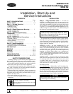
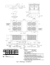
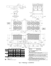
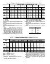
Table 1 — Rigging Center of Gravity — in. (mm)
UNIT
38AH
044 054 064 074 084 094 104
MODULE
124A
MODULE
124B
MODULE
134A
MODULE
134B
Dimension X 49 (1232) 48 (1224) 50 (1260) 57 (1443) 57 (1448) 66 (1676) 63 (1600) 50 (1260) — 50 (1260) —
Dimension Y 39 (984) 39 (978) 38 (968) 39 (993) 39 (991) 31 (787) 34 (851) 38 (968) — 38 (968) —
Dimension X-C 49 (1234) 48 (1229) 50 (1261) 56 (1425) 56 (1422) 66 (1676) 63 (1600) 50 (1260) — 50 (1260) —
Dimension Y-C 39 (993) 39 (991) 39 (986) 40 (1006) 40 (1008) 31 (787) 34 (851) 39 (986) — 39 (986) —
Dimension K ————————50(1260) — 57 (1443)
Dimension L ————————38(968) — 39 (993)
Dimension K-C ————————50(1260) — 56 (1425)
Dimension L-C ————————39(986) — 40 (1006)
LEGEND
——Not Applicable
C—Copper Fin Coils
TOP VIEW, TYPICAL
124, 134 ONLY
2