


Index
MN1904
I
Indicators, 6-2
axis LEDs, 6-2, 6-5
status display, 6-2, 6-5
Input / Output
analog I/O, 4-4
analog inputs - X3, 4-4, 7-1
analog outputs (Demands) - X7, 4-6, 7-2
CAN - X16 & X17, 4-20
connection summary, 4-23
digital I/O, 4-7
digital inputs (Interrupts) - X6, 4-10, 7-2
digital inputs - X1, 4-8, 7-2
digital inputs - X2, 4-9, 7-2
digital outputs - X4, 4-11, 7-3
encoder interfaces - X9-X13, 4-12, 7-3
relay and user power - X5, 4-14, 7-3
RS232 - X15, 4-15
connecting Baldor HMI panels, 4-17
RS422/RS485 - X14, 4-18
Installation, 3-1
dimensions, 3-4
mechanical, 3-3
mounting, 3-4
Interrupts - X6, 4-1 0
Introduction to closed loop control, 5-11
L
LED indicators
axis LEDs, 6-2, 6-5
status display, 6-2, 6-5
Loading saved information, 5-28
M
Mounting, 3-4
O
Operation, 5-1
connecting to the PC, 5-1
installing the software, 5-1
power on checks, 5-2
preliminary checks, 5-1
starting, 5-1
Overdamped response, 5-17
P
PC Hardware requirements, 3-1
Power
connections - X8, 4-3
sources, 3-1
Precautions, 1-2
R
Receiving and Inspection, 2-2
Relay, 4-14
specifications, 7-3
Reset states, 4-22
RS232, 4-15
RS422/RS485, 4-18
S
Safety Notice, 1-2
Saving setup information, 5-27
Scale, selecting, 5-6
Serial connections
RS232, 4-15
RS422/RS485, 4-18
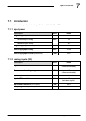
Specifications, 7-1
analog inputs - X3, 7-1
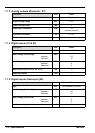
analog outputs (Demands) - X7, 7-2
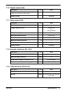
CAN interfaces - X16 & X17, 7-3
digital inputs (Interrupts) - X6, 7-2
digital inputs - X1 & X2, 7-2
digital outputs - X4, 7-3
encoder interfaces - X9-X13, 7-3
environmental, 3-3, 7-4
input power , 7-1
relay output - X5, 7-3
weights and dimensions, 3-4, 7-4
Status display, 6-2, 6-5
System watchdog, 4-22