


Input / Output 4-11MN1904
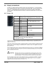
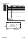
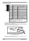
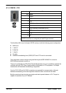
4.6.4 Digital outputs - X4
Location Connector X4
(Mating connector: Weidmüller BL 3.5/10, 3.5mm pitch)
Pin Name Mint keyword / description
1 DOUT0 OUTX.0
2 DOUT1 OUTX.1
3 DOUT2 OUTX.2
4 DOUT3 OUTX.3
5 DOUT4 OUTX.4
6 DOUT5 OUTX.5
7 DOUT6 OUTX.6
8 DOUT7 OUTX.7
9 USR V+ Customer power supply V+
10 CGND Customer power supply ground
Description
Eight general purpose optically isolated digital outputs.
Output current: 50mA maximum (continuous) each output
Update interval: Immediate
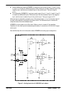
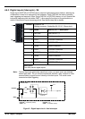
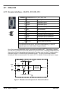
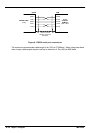
Each optically isolated output is designed to source current from the customer supplied
12-24V supply (USR V+) as shown in Figure 6. The outputs can be written to directly using
the Mint keyword OUTX (for example OUTX.2=1).
The sense of the outputs can be configured in WorkBench v5, and their states are displayed in
the Spy window. The use of shielded cable is recommended.
OUTX.x
USR V+
NextMove BX
II
DOUTx
CGND
Output
load
UDN2987
Output
module
TLP121
Figure 6 - Digital output c ircuit
The USR V+ and CGND connections on pins 9 and 10 are connected internally to the USR V+
and CGND pins on connector X5. See section 4.7.3.
1
10