


Input / Output 4-23MN1904
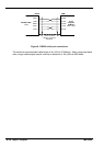
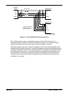
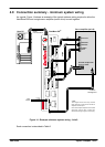
4.9 Connection summary - minimum system wiring
As a guide, Figure 14 shows an example of the typical minimum wiring required to allow the
NextMove BX
II
and a single servo amplifier (motor drive) to work together.
Host PC NextMove BX
II
Servo amplifier (axis 0)
Encoder output from
drive or motor
Error out
Gnd*
Enable*
Demand -
Demand +
*Note:
This diagram shows the relay contacts
being used as a switch across the servo
amplifier’s enable input.
Iftheservoamplifierrequiresa24Venable
signal then use the relay to switch 24V
fromeitherthe logicsupply orusersupply.
Serial
communication
+24V
supply
Common
earth/ground
Figure 14 - Example minimum system wiring - Axis 0
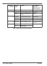
Each connection is described in Table 2.