


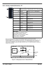
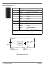
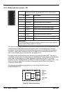

4-14 Input / Output MN1904
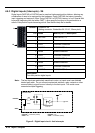
4.7.3 Relay and user power - X5
Location Connector X5
(Mating connector: Weidmüller BL 3.5/10, 3.5mm pitch)
Pin Name Description
1 Relay COM Common relay connection
2 Relay NC Normally closed relay connection
3 Relay NO Normally open relay connection
4 Relay COM Common relay connection
5 USR V+ Digital output customer power supply
6 USR V+ Digital output customer power supply
7 CREF D igital input common connection
8 CREF D igital input common connection
9 CGND Digital output customer power supply ground
10 CGND Digital output customer power supply ground
Description
Connection point for the digital outputs’ customer power supply and the
relay contacts. Relay rated at 1A, 24VDC
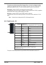
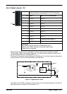
The relay and user power connector X5 provides a connection point for the internal relay , the
customer power supply used to power the digital outputs, and the digital input’s common
connection. Power connections are assigned two pins to provide increased wiring capacity.
The USR V+ and CGND connections on pins 5/6 and 9/10 are connected internally to the
USR V+ and CGND pins on connector X4 - see section 4.6.4.
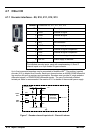
The relay outputs are isolated from any internal circuits in the NextMove BX
II
.Therelayis
controlled by a latch, which is cleared when the NextMove BX
II
resets. Reset can occur due to
power-down, a watchdog error or when deliberately caused by the host PC. In normal
operation the relay is energized and the Relay NC contact is connected to Relay COM. In the
event of an error or power loss, the relay is de-energized and the Relay NO contact is
connected to Relay COM.
The relay can be configured as a global error output using the Mint keyword
GLOBALERROROUTPUT.
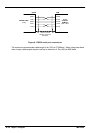
Relay NC
Pin 2
Relay COM
Pin 1
Relay
Mint
NextMove BX
II
Relay NO
Pin 3
Figure 8 - Relay conne c tions