


4-4 Input / Output MN1904
4.5 Analog I/O
The NextMove BX
II
provides:
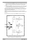
H Eight 12-bit resolution analog inputs, available on connector X3.
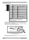
H Four 14-bit resolution analog outputs, available on connector X7.
Sections 4.5.1 to 4.5.2 describe each analog input and output.
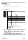
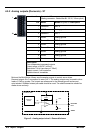
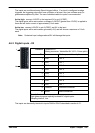
4.5.1 Analog inputs - X3
Location Connector X6
(Mating connector: Weidmüller BL 3.5/10, 3.5mm pitch)
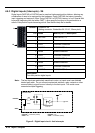
Pin Name MintMT keyword / description
1 AIN0 ADC.0
2 AIN1 ADC.1
3 AIN2 ADC.2
4 AIN3 ADC.3
5 AIN4 ADC.4
6 AIN5 ADC.5
7 AIN6 ADC.6
8 AIN7 ADC.7
9 AGND Analog ground
10 Shield Shield connection
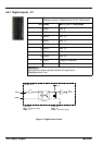
Description
Single ended or differential inputs
Voltage range: software selectable 0-5V, ±2.5V, ±10V
Resolution: 12-bit with sign (accuracy ±4.9mV @ ±10V input)
Input impedance: >20kΩ
Sampling interval: 222µs - 2ms
The Mint keyword ADCMODE can be used to setup various configurations for the analog inputs.
H Single ended (ADCMODE 0): This is the default configuration. Each input behaves as a
single ended, unipolar input with an input range of 0-5V. The input’s 0V connection is
connected to pin 9, AGND.
H Single ended, bipolar (ADCMODE 2): Each input is a single ended, bi-polar input with an
input range of ±5V. The input’s 0V connection is connected to pin 9, AGND.
H Pseudo differential (ADCMODE 1): Inputs are used in pairs (0 and 1, 2 and 3, 4 and 5, 6 and
7) to create four differential inputs. Within each pair, the odd numbered input is the
negative input, and the even numbered input is the positive input. The input range is 0 -
5V.