


4-12 Input / Output MN1904
4.7 Other I/O
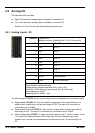
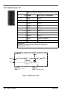
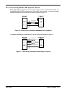
4.7.1 Encoder interfaces - X9, X10, X1 1, X12, X13
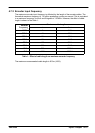
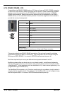
Location Connectors X9, X11, X11, X12, X13
Pin Name Description
1 CHA+ C hannel A signal
2 CHB+ C hannel B signal
3 CHZ+ Index channel signal
4 (NC) Not connected
5 DGND Power supply ground
6 CHA- Channel A signal complement
7 CHB- Channel B signal complement
8 CHZ- Index channel signal complement
9 +5V out Power supply to encoder
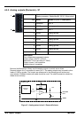
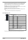
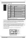
Description
Five identical encoder inputs, each with complementary A, B and Z
channel inputs on a 9-pin female D-type connector
Up to five incremental encoders may be connected to NextMove BX
II
. The auxiliary (master)
encoder (X13) is labeled Aux Encoder . Each input channel enters an AM26LS32AM differential
line receiver with pull up resistors and terminators. Encoders must provide 5V single ended or
differential signals, or RS422/RS485 differential signals. The use of individually shielded
twisted pair cable is recommended. See section 4.4.1 for details of the encoder power supply.
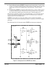
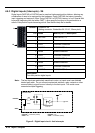
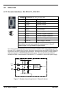
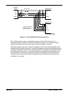
CHA-
Pin 6
CHA+
Pin 1
Vcc
NextMove BX
II
22R
22R
120R
2k2
2k2
AM26LS32
Differential
line receiver
to CPU
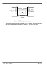
Figure 7 - Encoder channe l input circuit - Channel A shown
1
5
6
9